

Runner layer structure of PTC electric heating device
An electric heating device and layer structure technology, applied in water heaters, fluid heaters, lighting and heating equipment, etc., can solve the problem of increasing the pressure load of the flow medium pipeline of the power pump in the heating system, reducing the heating power of the PTC heating element, heating Problems such as excessive pressure difference between the inlet and outlet of the device, to avoid excessive local temperature, improve heat transfer effect, and high heat transfer efficiency
- Summary
- Abstract
- Description
- Claims
- Application Information
AI Technical Summary
Problems solved by technology
Method used
Image

Examples
Embodiment Construction
[0014] The present invention will be described in further detail below in conjunction with the accompanying drawings.
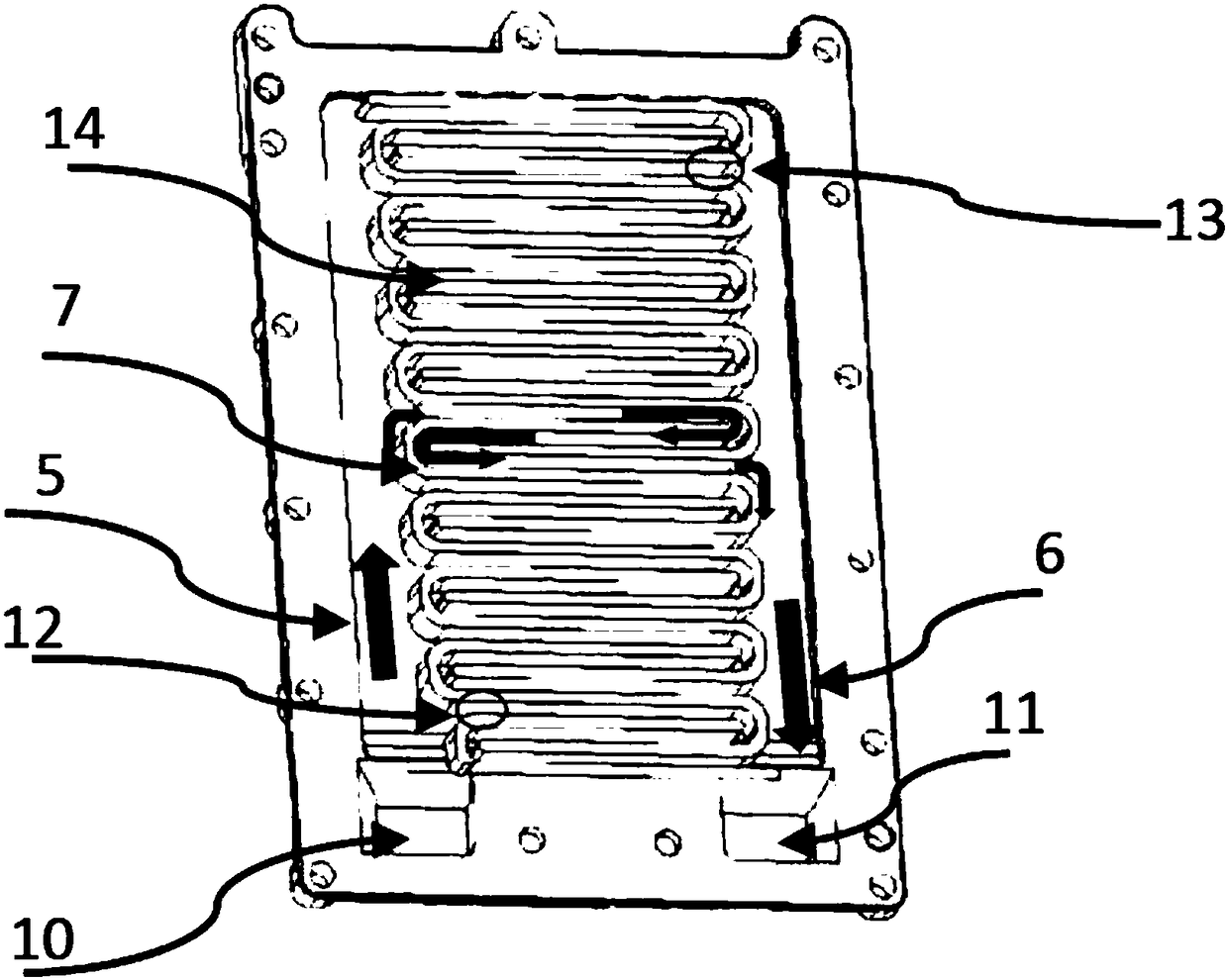
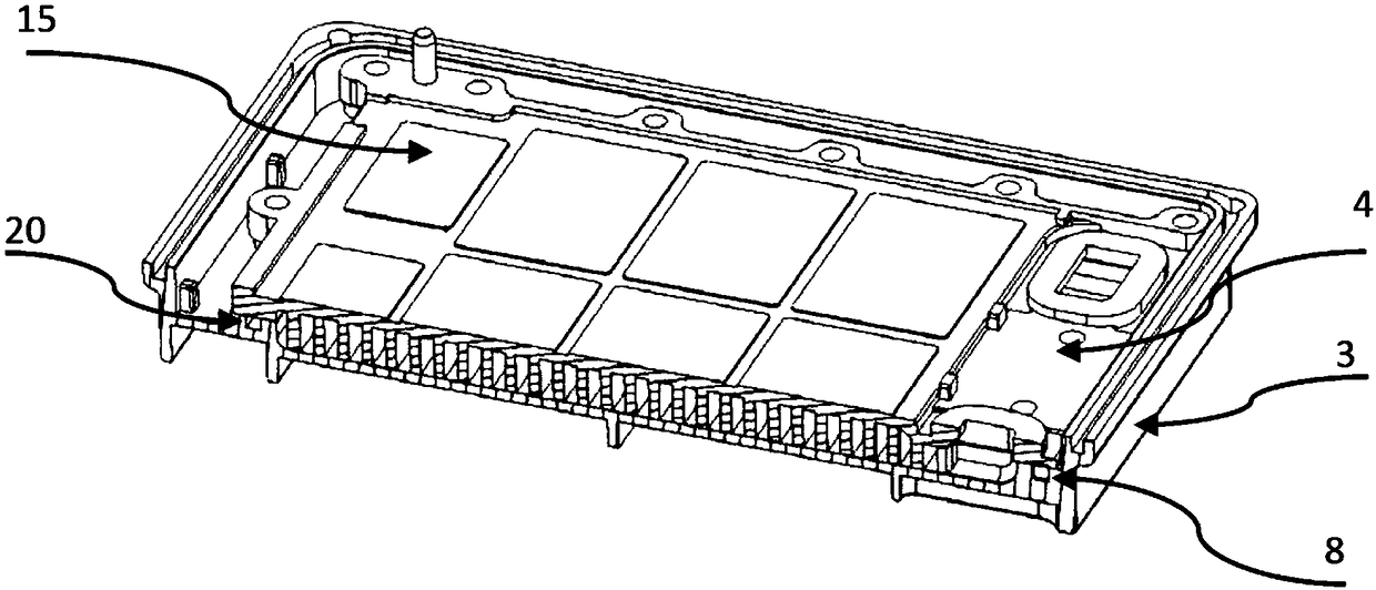
[0015] combined with figure 1 And attached figure 2 , a flow channel layer structure of a PTC electric heating device, which includes a lower casing 3, an upper casing 4 and a sealing element 8, at least one of the lower casing 3 and the upper casing 4 is attached to a PTC heating element, The lower casing 3 or the upper casing 4 is provided with a groove 20 for installing the sealing element 8, and the lower casing 3 and the upper casing 4 are formed by pressing with the sealing element 8 to form an external opening with only an inlet. 10 and the assembly of the outlet 11; the assembly is provided with an inlet main channel 5, an outlet main channel 6 and a branch flow channel 7 composed of several heat exchange fins 14; the branch flow channel 7 is S-shaped, The several branch flow channels 7 introduce the flow medium in the inlet main channel 5 into the...
PUM
 Abstract
Description
Claims
Application Information