Method and apparatus for correcting stripes-crossing output of three-axis optical-fiber gyroscope by using MEMS

A fiber optic gyroscope and gyroscope technology, applied in the direction of measuring devices, instruments, etc., can solve the problems of cross-stripe, single-stripe working area reduction, low working accuracy of fiber optic gyroscope, etc., achieve small changes, facilitate implementation, and improve accuracy.

Active Publication Date:
View PDF7 Cites 8 Cited by
  • Summary
  • Abstract
  • Description
  • Claims
  • Application Information

AI Technical Summary

Problems solved by technology

[0004] It can be seen that the existing technology mainly adopts the method of expanding the measurement range on the problem of gyroscope stripe measurement. Although expanding the cross-stripe measurement range or single-stripe measurement range of the fiber optic gyroscope can solve the problem of the fiber optic gyroscope measurement range, these methods are all aimed at The problem of low working accuracy of the fiber optic gyroscope in the case of large angle or rotation does not substantially solve the problem of the reduction of the single stripe working area of ​​the fiber optic gyroscope when the effective diameter of the fiber optic ring increases and the length of the fiber increases.
Therefore, it is necessary to propose a more effective solution to the problem that the fiber optic gyroscope is less likely to occur in the single-stripe working range and is more prone to cross-stripe phenomena under large-scale vibration and shock conditions.

Method used


Image

  • Method and apparatus for correcting stripes-crossing output of three-axis optical-fiber gyroscope by using MEMS
  • Method and apparatus for correcting stripes-crossing output of three-axis optical-fiber gyroscope by using MEMS
  • Method and apparatus for correcting stripes-crossing output of three-axis optical-fiber gyroscope by using MEMS

Examples


Embodiment Construction

[0033] In order to make the object, technical solution and advantages of the present invention clearer, the present invention will be further described in detail below in conjunction with the accompanying drawings and embodiments. It should be understood that the specific embodiments described here are only used to explain the present invention, not to limit the present invention. In addition, the technical features involved in the various embodiments of the present invention described below can be combined with each other as long as they do not constitute a conflict with each other. The present invention will be further described in detail below in combination with specific embodiments.

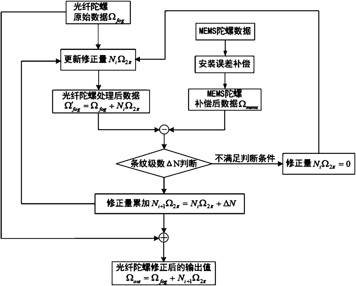
[0034] In the embodiment of the present invention, a MEMS-based method for correcting the output of a high-precision three-axis fiber optic gyroscope across stripes is proposed. On the basis of the existing three-axis fiber optic gyroscope, a three-axis MEMS gyroscope chip is added to reali...


PUM


Abstract

The invention discloses a method for correcting stripes-crossing output of a three-axis optical-fiber gyroscope by using MEMS. The method comprises the following steps: acquiring original output parameters of the MEMS gyroscope corresponding to three axial directions of the optical-fiber gyroscope by using an MEMS chip; performing error compensation for the original output parameters of the MEMS gyroscope, and then converting into an optical-fiber gyroscope coordinate system; setting an initial correction value of the optical-fiber gyroscope according to a working stripe series of the optical-fiber gyroscope; acquiring a parameter difference of the correction data of the optical-fiber gyroscope and the MEMS gyroscope data according to the acquired optical-fiber gyroscope data, the MEMS gyroscope data and/or the initial correction value; and determining the stripe adjusting series by utilizing the parameter difference, determining a real-time correction value of the optical-fiber gyroscope, and correcting and outputting the optical-fiber gyroscope data by using the optical-fiber gyroscope correction value. The technical scheme of the invention also discloses an apparatus for correcting the stripes-crossing output of the three-axis optical-fiber gyroscope by using MEMS. By adopting the method, the stripes-crossing problem caused by the intrinsic characteristics of the optical-fiber gyroscope in a severe dynamic environment can be solved, and the output reliability of the optical-fiber gyroscope can be ensured.

Description

technical field [0001] The invention belongs to the field of optical fiber gyroscope measurement, and in particular relates to a method and a device for correcting the cross-stripe output of a three-axis optical fiber gyroscope by using MEMS. Background technique [0002] Fiber optic gyro is an angular rate sensor based on the Sagnac effect. Due to its low cost, simple process, high reliability, and strong shock and vibration resistance, it also has an all-solid-state structure, shock resistance, large dynamic range, wide frequency band, and easy digitization. Realization and other advantages, the application prospect is highly valued, has become one of the mainstream sensors, widely used in aviation, aerospace, navigation and other important fields. Accuracy is an important measure of fiber optic gyroscope performance. At present, the fiber optic gyro mainly improves the accuracy by increasing the effective diameter of the fiber optic ring and lengthening the length of the...

Claims


Application Information

Patent Timeline
Patent Type & Authority Applications(China)
IPC IPC(8): G01C25/00
CPCG01C25/005
Inventor 高枫孙娜袁慧铮张庆伟
Why Eureka
Try Eureka