
Immunofluorescence detection light path mechanism, immunofluorescence detection instrument and calibration method of immunofluorescence detection instrument

An immunofluorescence detection and immunofluorescence technology, applied in the field of immunofluorescence detection, can solve the problems of large deviation of test results and large CV value of test instruments, and achieve the effect of reducing CV value and improving accuracy

Pending Publication Date: 2018-09-14
GUANGZHOU WONDFO BIOTECH
View PDF0 Cites 9 Cited by
  • Summary
  • Abstract
  • Description
  • Claims
  • Application Information

AI Technical Summary

Problems solved by technology

[0005] Based on this, it is necessary to provide a method to ensure the uniformity of the test results of the immunofluorescence detection instrument, reduce the CV value of different test instruments, and improve the accuracy of the test for the problems of large deviations in test results and large CV values ​​​​of the traditional immunofluorescence detection instruments. Immunofluorescence detection optical path, immunofluorescence detector and calibration method thereof

Method used


Image

  • Immunofluorescence detection light path mechanism, immunofluorescence detection instrument and calibration method of immunofluorescence detection instrument
  • Immunofluorescence detection light path mechanism, immunofluorescence detection instrument and calibration method of immunofluorescence detection instrument
  • Immunofluorescence detection light path mechanism, immunofluorescence detection instrument and calibration method of immunofluorescence detection instrument

Examples


Embodiment Construction

[0029] In order to facilitate the understanding of the present invention, the present invention will be described more fully below with reference to the associated drawings. Preferred embodiments of the invention are shown in the accompanying drawings. However, the present invention can be embodied in many different forms and is not limited to the embodiments described herein. On the contrary, these embodiments are provided to make the understanding of the disclosure of the present invention more thorough and comprehensive.

[0030] It should be noted that when an element is referred to as being “fixed” to another element, it can be directly on the other element or there can also be an intervening element. When an element is referred to as being "connected to" another element, it can be directly connected to the other element or intervening elements may also be present. The terms "vertical," "horizontal," "left," "right," and similar expressions are used herein for purposes ...


PUM


Abstract

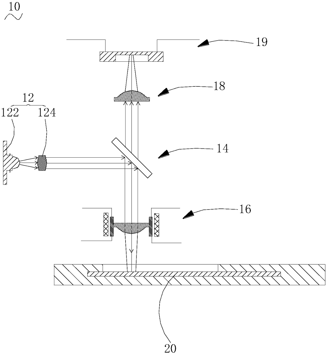
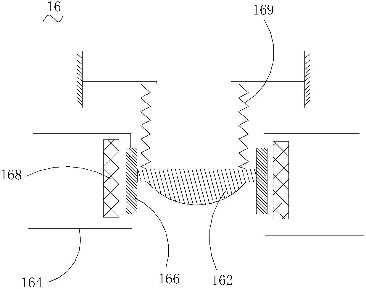
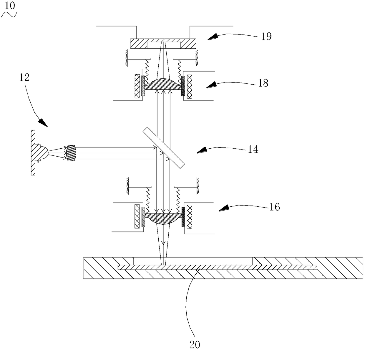
The invention relates to an immunofluorescence detection light path mechanism. The immunofluorescence detection light path mechanism comprises a light source generation device, an optical two-phase sub-mirror, a first convergent lens component, a second convergent lens component and a fluorescence collection device, the optical two-phase sub-mirror is arranged on a transmission light path of a light source, the first convergent lens component and the second convergent lens component are respectively located the light path of the optical two-phase sub-mirror and a light path of transmission light, the fluorescence collection device is located on one side, far from the optical two-phase sub-mirror, of the second convergent lens component; and the first convergent lens component is configuredto do rectilinear motion along the direction of a light path of reflection light of the optical two-phase sub-mirror according to an electric signal applied on the first convergent lens component. Therefore, the fluorescence values of fluorescence test papers of a same to-be-detected sample detected by multiple immunofluorescence detection instruments are unified, the influence on the numerical value of the test result caused by the difference of parts in the instrument and the difference produced in the production and assembly is reduced, and the testing accuracy is improved. The invention further provides the immunofluorescence detection instrument and a calibration method of the immunofluorescence detection instrument.

Description

technical field [0001] The invention relates to the technical field of immunofluorescence detection, in particular to an immunofluorescence detection optical path mechanism, an immunofluorescence detector and a calibration method thereof. Background technique [0002] The basic principle of immunofluorescence technology is to organically combine the high specificity of antigen-antibody reaction with the sensitivity and measurability of fluorescence, and use fluorescent substances as tracers to mark antigens or antibodies to make specific reagents for detecting the corresponding Antibody or antigen technology. Specifically, a specific light source is used to irradiate the fluorescent substance in the antigen-antibody conjugate, and the fluorescent substance is excited to radiate fluorescence, which can be observed or quantitatively detected by an analyzer to detect and locate the function of a specific substance. Because of its advantages of accuracy, specificity, sensitivit...

Claims


Application Information

Patent Timeline
Patent Type & Authority Applications(China)
IPC IPC(8): G01N33/533G01N21/64G01N21/01
CPCG01N21/01G01N21/64G01N21/6428G01N33/533G01N2021/6463G01N2021/0112
Inventor 黄仁宏胡海升王继华
Owner GUANGZHOU WONDFO BIOTECH
Learn More