
Leather collar under pin and its application

A kind of apron and the corresponding technology, applied in the field of spun yarn drafting, can solve the problems of not being able to effectively control the yarn sliver, not enough, weakening the strength of the main drafting area, etc.

Inactive Publication Date: 2004-12-29
汤永学
View PDF0 Cites 0 Cited by
  • Summary
  • Abstract
  • Description
  • Claims
  • Application Information

AI Technical Summary

Problems solved by technology

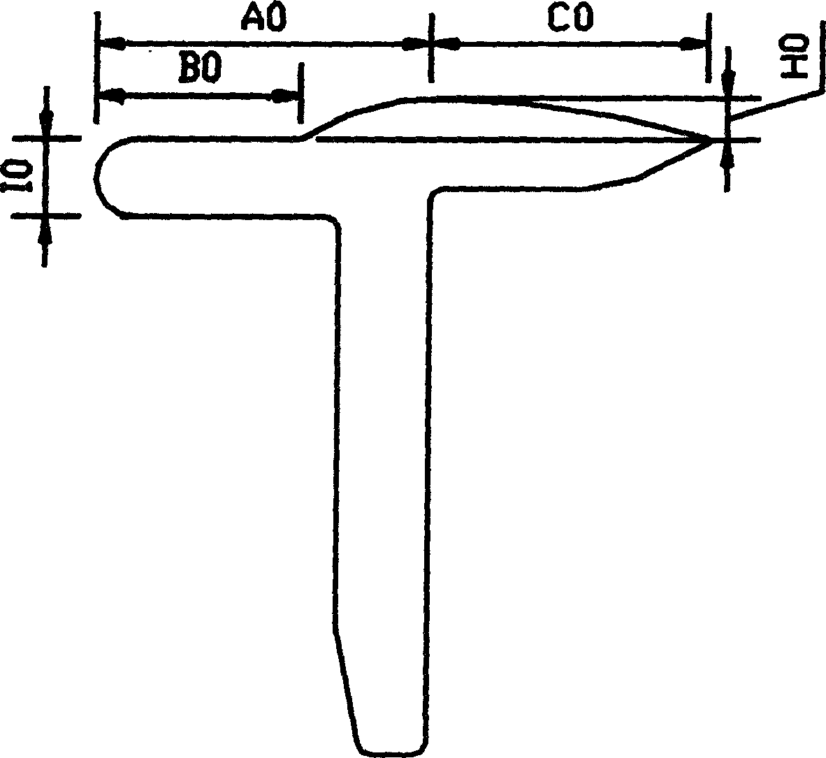
However, further research and experiments have shown that the lower pin of this shape cannot effectively control the drafted sliver fibers, and there is room for improvement
Its design flaws are: the length of the straight line (plane) part of the lower pin is longer, making the elastic force of the supporting apron weaker, weakening the strength of the friction force circle in the middle of the main drafting area, and the control force on the sliver is not enough Strong; the lifting force of the highest point of the lower pin curve is not enough, so that the drafting channel of the sliver curve formed by the apron is relatively gentle, and the sliver cannot be controlled strongly, which is not conducive to the high quality of the yarn

Method used


Image

  • Leather collar under pin and its application
  • Leather collar under pin and its application
  • Leather collar under pin and its application

Examples


Embodiment 1

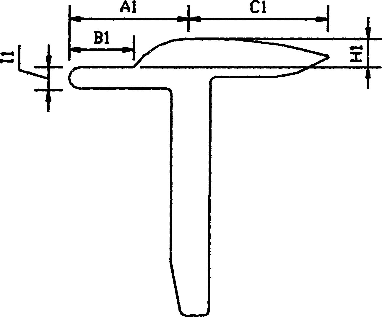
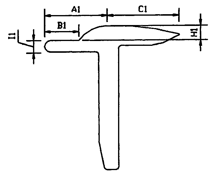
[0014] Experimental model: A512V, DVX pneumatic pressure; spinning 40 counts of combed cotton yarn; the structural size of the lower pin using the apron is: the length of the straight part B1 is 6 mm; the length of the curved part connected with the straight part B1 is 18 mm, and the distance A1 from the highest point to the front edge of the straight part is 11 mm, and the distance C1 from the highest point to the tail end of the lower pin of the apron is 13 mm; the thickness I1 of the straight part is 2 mm, and the height between the curved part and the straight part The difference H1 is 2.5 mm. The experimental results are shown in Table 1:

[0015] indicators

Embodiment 2

[0017] Experimental model: FA506, DVX pneumatic pressurization; spinning combed cotton / polyester 55 / 45 45 count yarns; the structure size using the lower pin of the apron is: the straight part B17.9mm; the curved part connected with the straight part B1 16.1 mm, and the distance A1 from the highest point to the front edge of the straight part is 12.9 mm, and the distance C1 from the highest point to the tail end of the lower pin of the apron is correspondingly 11.1 mm; the thickness I1 of the straight part is 1.5 mm, and the distance between the curved part and the straight part The height difference H1 is 3.0 mm. The experimental results are shown in Table 2:

[0018] indicators

Embodiment 3

[0020] The experimental machine is the same as in Example 1; spinning combed cotton / polyester 60 / 40 45 count yarns; the structural size of the lower pin using the apron is: B1 length 5 mm; the length of the curved part is 19 mm, and its highest point is away from the straight line part The distance A1 of the leading edge is 11 millimeters, and the distance C1 of the highest point from the tail end of the lower pin of the apron is 13 millimeters accordingly; The experimental results are shown in Table 3:

[0021] indicators


PUM

PropertyMeasurementUnit
lengthaaaaaaaaaa
thicknessaaaaaaaaaa
lengthaaaaaaaaaa

Abstract

The present invention relates to the lower apron pin technology of the drafting mechanism of the spinning frame. A kind of apron lower pin is designed. Its random cross-section has the same shape, which is basically T-shaped, and the upper surface of the T-shaped horizontal part is a section. A combined shape connected by a straight line and a section of curve, the curved section is higher than the straight section and has a height difference, and the straight section has a certain thickness, characterized in that the length of the section of the straight section is 5-7.9 mm; the curved section connected with the straight section The length of the straight part is 19-16.1 mm, and the distance from the highest point to the front edge of the straight part is 10-12.9 mm; the thickness of the straight part is 1.5-2.9 mm, and the height difference between the curved part and the straight part is 3.0- 1.6mm. It has better control over drafting sliver, significantly improved yarn quality, simple structure and wide adaptability.

Description

technical field [0001] The invention relates to spinning drafting technology, specifically the apron lower pin of the spinning frame drafting mechanism, and the international patent main classification number is intended to be Int.Cl 7 .DOIH5 / 88. Background technique [0002] At present, the drafting mechanism of the ring spinning machine in the spinning mill generally adopts long and short double aprons, spring swing pins, spring cradle pressurization or pneumatic cradle pressurization devices, mainly relying on drafting rollers, rubber rollers, aprons, elastic The upper pin and the curved surface stepped lower pin work together to control the fiber and achieve drafting. The intermediate additional friction circle formed by the mechanism composed of aprons, elastic upper pins and curved surface stepped lower pins plays a decisive role in controlling fiber movement and ensuring the quality of the drafted yarn, especially the apron, elastic upper pins and curved surface step...

Claims


Application Information

Patent Timeline
Patent Type & Authority Patents(China)
IPC IPC(8): D01H1/02D01H5/88
Inventor 杨玉奇韩文杰段昭一王东明
Owner 汤永学
Learn More