
Array substrate, manufacturing method thereof, and display device

A technology of an array substrate and a manufacturing method, which is applied to semiconductor/solid-state device parts, instruments, semiconductor devices, etc., and can solve the problem of short circuit of data lines 14 and parallel signal lines 12, failure of sub-pixels to provide data voltage, and failure of sub-pixels to display normally and other problems, to achieve the effect of reducing the occurrence of short circuits, improving the display effect, and reducing the grid phenomenon

Active Publication Date: 2020-07-17
BOE TECH GRP CO LTD +1
View PDF14 Cites 0 Cited by
  • Summary
  • Abstract
  • Description
  • Claims
  • Application Information

AI Technical Summary

Problems solved by technology

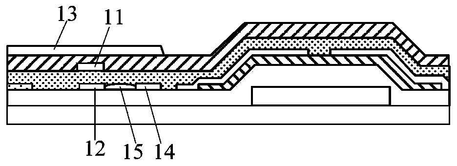
Affected by foreign matter such as dust, it is easy to cause not only the data line 14 and the parallel signal line 12 to be formed in the patterning process, but also the conductive residual part 15 between the data line 14 and the parallel signal line 12 is likely to be generated, which will lead to data Short circuit between line 14 and parallel signal line 12
Since the touch electrode 13 is multiplexed as a common electrode in the display phase, that is, the parallel signal line 12 is loaded with a common voltage signal in the display phase, therefore, when the data line 14 and the parallel signal line 12 are short-circuited, the voltage on the data line 14 It will be pulled down to the common voltage on the parallel signal line 12, so that during the display process, the data line 14 cannot provide the required data voltage for the sub-pixels, and then the sub-pixels cannot be displayed normally, resulting in poor grid

Method used


Image

  • Array substrate, manufacturing method thereof, and display device
  • Array substrate, manufacturing method thereof, and display device
  • Array substrate, manufacturing method thereof, and display device

Examples


Embodiment Construction

[0038] Specific embodiments of the present invention will be described in detail below in conjunction with the accompanying drawings. It should be understood that the specific embodiments described here are only used to illustrate and explain the present invention, and are not intended to limit the present invention.

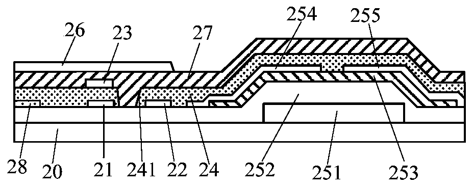
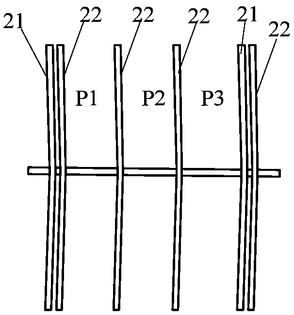
[0039] As an aspect of the present invention, an array substrate is provided, such as figure 2 As shown, it includes a substrate 20 , a first signal line 21 and a second signal line 22 disposed on the substrate 20 , and an insulating layer 24 . Wherein, the first signal line 21 and the second signal line 22 are arranged on the same layer and spaced apart from each other, the insulating layer 24 covers the first signal line 21 and the second signal line 22, and a groove 241 penetrating through the insulating layer 24 is formed on the insulating layer 24 , the position of the groove 241 corresponds to the interval area between the first signal line 21 and the se...


PUM


Abstract

The present invention provides an array substrate, comprising: a substrate; a first signal line and a second signal line arranged on the substrate, the first signal line and the second signal line are arranged on the same layer and spaced from each other an insulating layer covering the first signal line and the second signal line; a groove penetrating the insulating layer is formed on the insulating layer, and the groove extends to the first signal line and the second signal line; The bottom surface of the layer where the two signal lines are located separates the first signal line from the second signal line, so that the first signal line and the second signal line are insulated. Correspondingly, the present invention also provides a method for manufacturing an array substrate and a display device. The present invention can reduce grid defects.

Description

technical field [0001] The present invention relates to the field of display technology, in particular to an array substrate, a manufacturing method thereof, and a display device. Background technique [0002] The touch display panel includes an external touch display panel and an in-cell touch display panel. The in-cell touch display panel is widely used because of its high light transmittance and thin thickness. The in-cell touch display panel can be divided into a mutual capacitive structure and a self capacitive structure. Among them, the self-capacitance structure includes a plurality of block-shaped touch electrodes, and each touch electrode is connected to the drive circuit through a touch signal line, and the drive circuit receives the signal change through each touch signal line and each touch control The coordinate position of the electrode determines the touch position. [0003] figure 1 It is a schematic structural diagram of an array substrate in a convention...

Claims


Application Information

Patent Timeline
Patent Type & Authority Patents(China)
IPC IPC(8): G06F3/041G06F3/044
CPCG06F3/0412G06F3/044G06F2203/04103H01L27/0248H01L27/124G06F3/047H01L23/3171H01L27/127
Inventor 刘冲赵海生肖志莲肖红玺王薇裴晓光
Owner BOE TECH GRP CO LTD
Learn More