Lathe fixture device

A lathe jig and jig technology, which is applied in positioning devices, clamping, manufacturing tools, etc., can solve the problems of single workstation, time-consuming, inability to improve processing efficiency, etc., and achieve the effect of jig optimization and work efficiency improvement.

Inactive Publication Date: 2018-09-18
李三源
View PDF0 Cites 8 Cited by
  • Summary
  • Abstract
  • Description
  • Claims
  • Application Information

AI Technical Summary

Problems solved by technology

[0004] Aiming at the deficiencies of the existing technology, the purpose of the present invention is to provide a lathe fixture device to solve the problem that the existing technical station is relatively single, and it is not conducive to on-site adjustment according to the workpiece processing angle requirements, and reprogramming the processing path is too expensive. Time, can not maximize the processing efficiency, the problem to be optimized

Method used


Image

  • Lathe fixture device
  • Lathe fixture device
  • Lathe fixture device

Examples


Embodiment

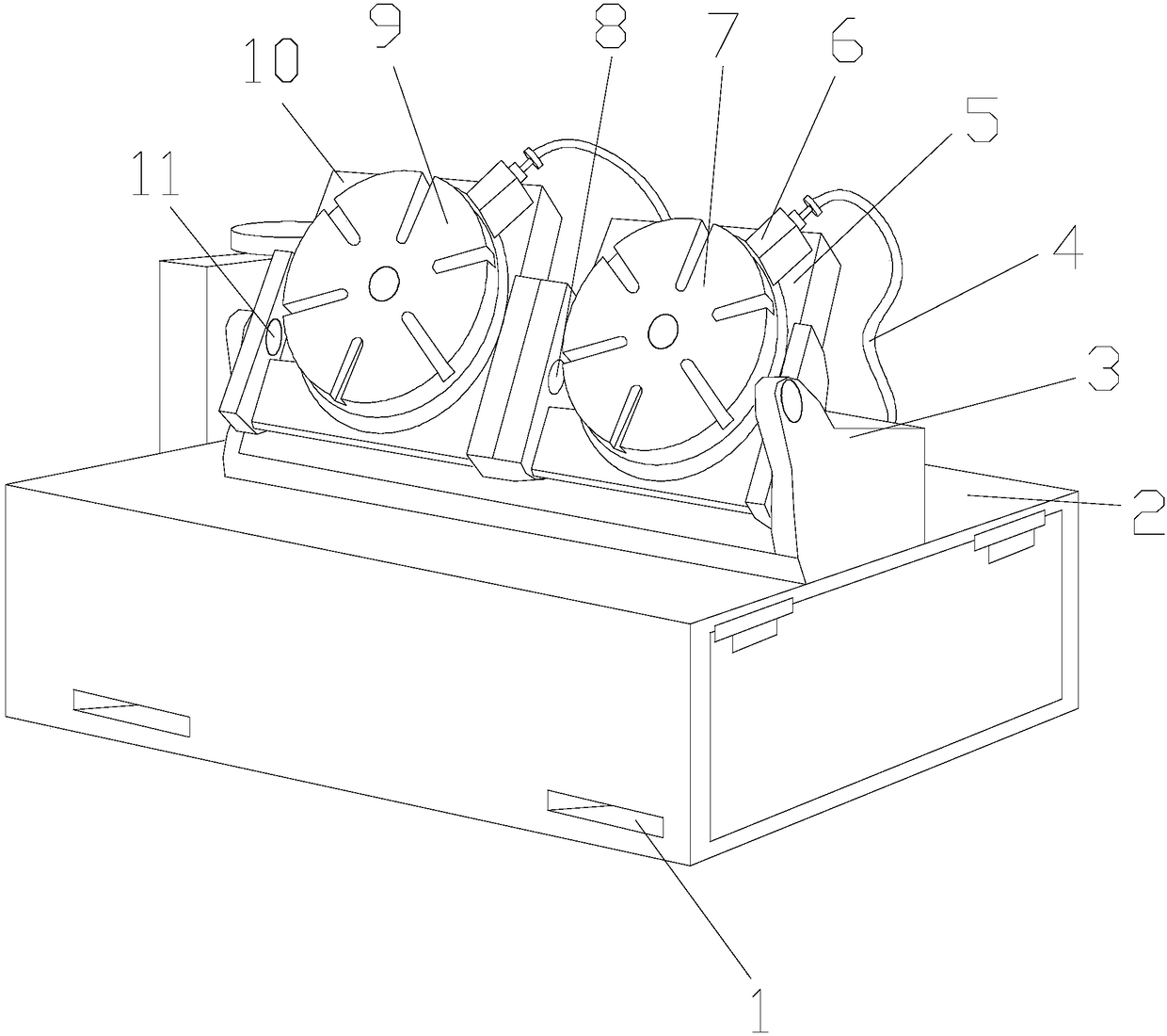
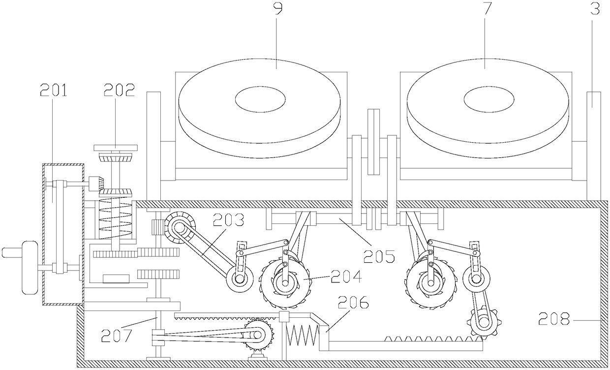
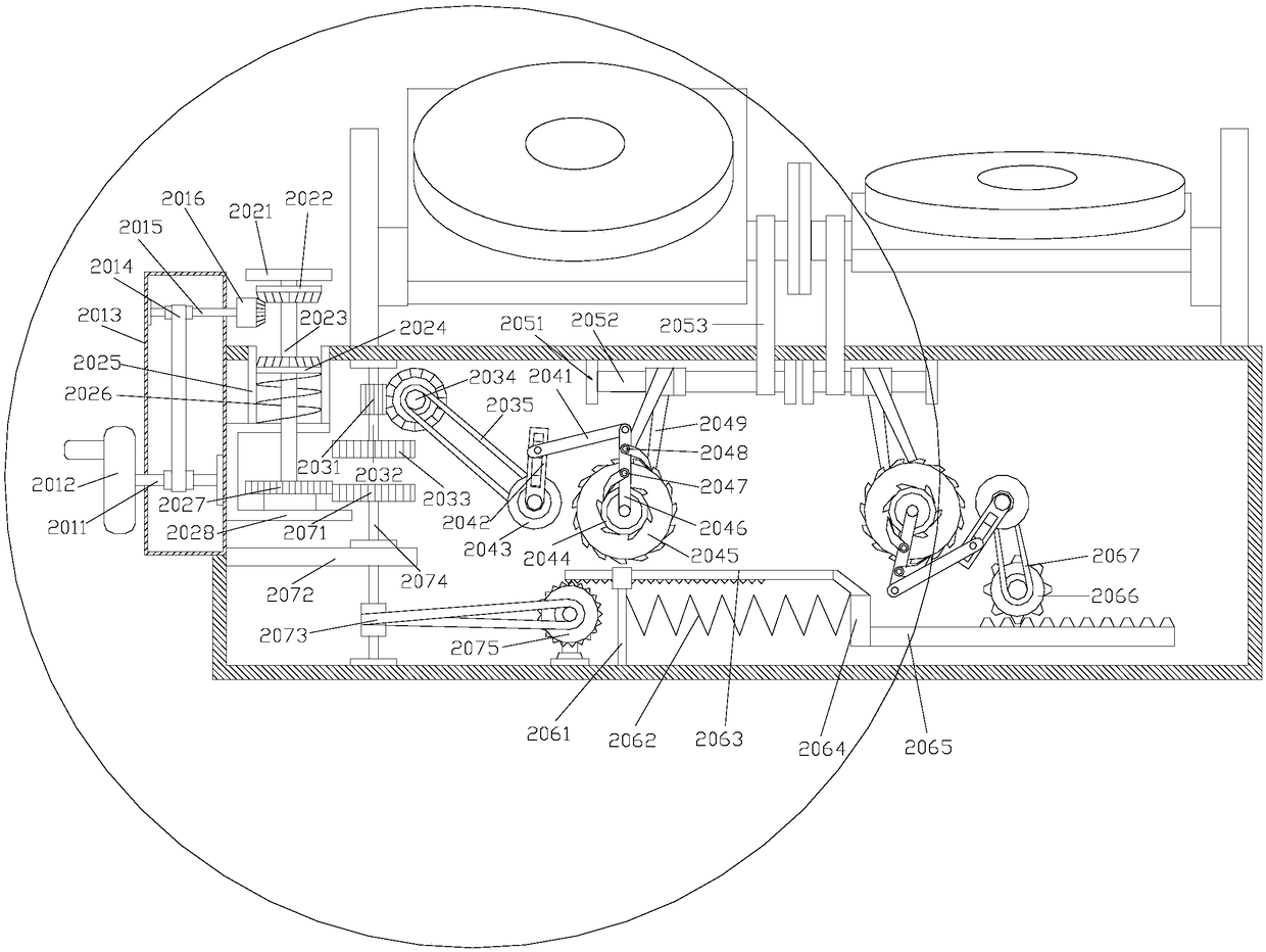
[0024] see Figure 1-Figure 4 , the present invention provides a lathe clamp device: its structure includes a positioning hole 1, a clamp base 2, a fixed frame 3, a vacuum tube 4, a first turning plate 5, a vacuum joint 6, a first clamp 7, a first turning shaft 8, a second Two fixtures 9, a second turning plate 10, and a second turning shaft 11, the positioning holes 1 are provided with more than two and are evenly and equidistantly distributed on the side of the fixture base 2, and the bottom of the fixed frame 3 is installed by buckling In the middle part of the upper end of the clamp base 2, the first turning plate 5 and the second turning plate 10 are fastened and mounted on the middle part of the fixed frame 3 through the first turning shaft 8 and the second turning shaft 11 respectively, and the first fixture 7 1. The bottom of the second clamp 9 is connected to the first flipping plate 5 and the second flipping plate 10 respectively by means of embedding, and the vacuum...


PUM


Abstract

The invention discloses a lathe fixture device. The lathe fixture device structurally comprises positioning holes, a fixture base, a fixing frame, a vacuum pipe, a first overturning plate, a vacuum connector, a first fixture, a first overturning shaft, a second fixture, a second overturning plate and a second overturning shaft. The two or more positioning holes are evenly distributed in the side face of the fixture base at equal intervals. The bottom of the fixing frame is installed on the middle portion of the upper end of the fixture base in a buckled manner. The lathe fixture device has thebeneficial effects that when double-station angle adjusting is carried out in the fixture base, the adjusting stations are switched through a station switching mechanism, an adjusting drive device drives the station switching mechanism to conduct transmission with a first transmission mechanism and a second transmission mechanism, then, according to arranged stations, corresponding linkage mechanisms and angle control mechanisms are controlled to control the first overturning shaft and the second overturning shaft, the first overturning shaft and the second overturning shaft control the firstoverturning plate and the second overturning plate to conduct angle overturning correspondingly, and therefore on-site adjusting can be carried out according to the angle demands of workpiece machining, the operation of reprogramming a machining path is omitted, the working efficiency is greatly improved, and the fixture is further optimized.

Description

technical field [0001] The invention relates to a lathe clamp device, which belongs to the field of lathe clamp devices. Background technique [0002] In the field of mechanical processing, the cost of lathe processing is relatively low compared with that of machining centers, but because the processing method of the lathe itself determines its processing range, many parts cannot be processed on the lathe and have to rely on processing The machining center will undoubtedly increase the processing cost. However, although some parts are generally processed by the machining center in the sense of traditional processing, they can also be processed by the lathe through the innovation of the fixture. Therefore, for those skilled in the art, it is yet to be developed a lathe fixture device, so that the parts that need to be processed by the machining center can be processed by the lathe. [0003] The existing technical station is relatively single, and it is not conducive to on-si...

Claims


Application Information

Patent Timeline
Patent Type & Authority Applications(China)
IPC IPC(8): B23Q3/08B23Q1/52
CPCB23Q3/088B23Q1/52
Inventor 李三源
Owner 李三源
Why Eureka
Try Eureka