A method of fabricating a part by additive manufacturing

a technology of additive manufacturing and parts, applied in the direction of additive manufacturing processes, manufacturing tools, turbines, etc., can solve the problems of affecting the risk of collapsing in the fabrication bin, and the surface state is not uniform, so as to improve the overall holding of the part, and strengthen the mechanical strength of the supporting connection

Active Publication Date: 2019-01-24
SN DETUDE & DE CONSTR DE MOTEURS DAVIATION S N E C M A
View PDF1 Cites 7 Cited by
  • Summary
  • Abstract
  • Description
  • Claims
  • Application Information

AI Technical Summary

Benefits of technology

[0047]In some embodiments, at least one inter-support reinforcing portion is added to the digital model to connect together at least two adjacent support portions, said inter-support reinforcing portion being disjoint from the surface that is to be spared. Said inter-support reinforcing portion may be arranged transversely, e.g. perpendicularly to said adjacent support portions, and it may be arranged so as to pass under the surface that is to be spared. Installing inter-support reinforcement serves to reinforce the mechanical strength of the supports connected together in that way, e.g. so as to avoid certain supports deforming or creeping completely under the weight of the part. This serves to impr...

Problems solved by technology

Nevertheless, while making parts of complex shape, certain portions of the part are to be found temporarily cantilevered out to a great extent, or even to be without any support other than the underlying volume of non-solidified powder, which thus presents a risk of collapsing in the fabrication bin.
However, once fabrication has finished, and while those supports are being removed, residues remain at the interfaces between the supports and the part.
Consequently, the resulting part includes zones in which the surface state is not uniform.
Such...

Method used


Image

  • A method of fabricating a part by additive manufacturing
  • A method of fabricating a part by additive manufacturing
  • A method of fabricating a part by additive manufacturing

Examples


Embodiment Construction

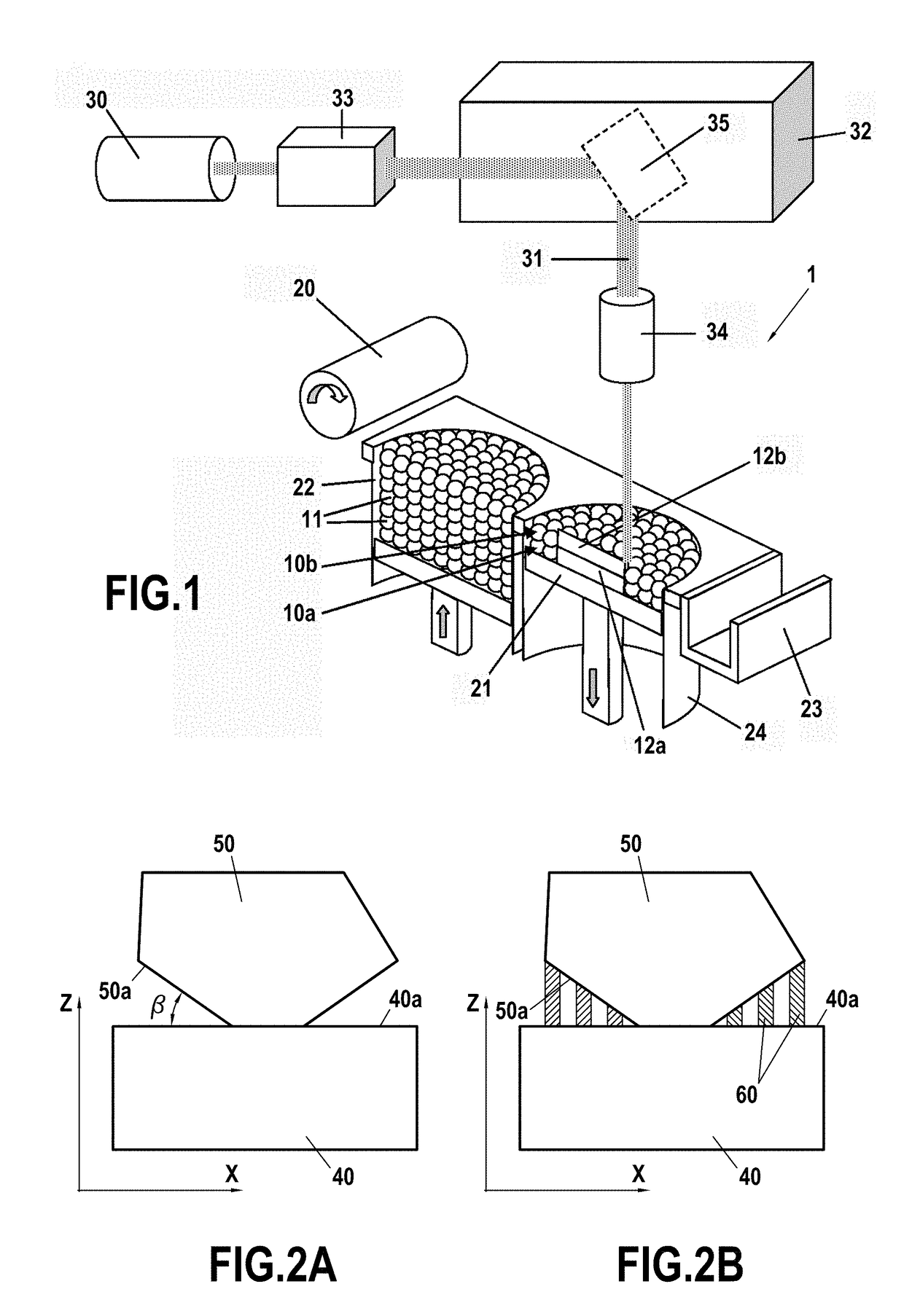
[0060]FIGS. 2A and 2B are elevation views of a model 50 of a part that is to be fabricated on a construction platform 40 by an additive method of fabricating a part. The direction of construction, corresponding to the axis Z, is perpendicular to the construction plane that corresponds to the top surface 40a of the construction platform 40. A surface 50a of the model 50 of the part presents a construction angle β relative to the surface 40a of the construction platform. When this construction angle β is less than 30°, the surface 50a runs the risk of collapsing during fabrication: it is then preferable to arrange supports 60 for the surface 50a of the model 50 of the part in order to hold this surface 50a while the part is being fabricated.

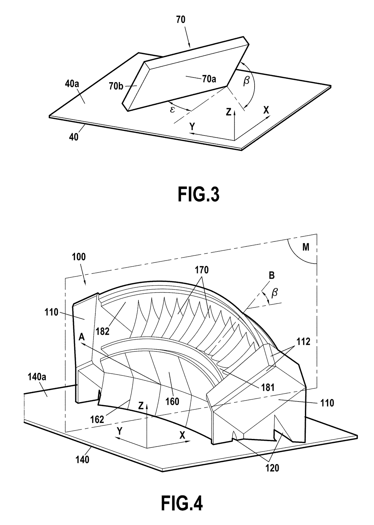
[0061]FIG. 3 is a perspective view of a model 70 of a portion that is elongate in the meaning of the present disclosure. The elongate portion has a front face 70b and a side face 70a, the front face 70b being narrower than the side face 70a. The co...


PUM

PropertyMeasurementUnit
Angleaaaaaaaaaa
Angleaaaaaaaaaa

Abstract

A method is for fabricating a part by additive manufacturing while sparing certain particularly sensitive surfaces of the part, and in particular surfaces that have an influence on the aerodynamics of the final part. The method includes the following steps: providing a digital model of a part that is to be fabricated, the part that is to be fabricated including at least one surface that is to be spared, and orienting the digital model relative to a construction direction wherein the part is to be constructed in such a manner that the surface that is to be spared presents a construction angle greater than 30°, preferably greater than 50°.

Description

FIELD OF THE INVENTION[0001]The present disclosure relates to a method of fabricating a part by additive manufacturing that serves to spare certain particularly sensitive surfaces of the part, and in particular surfaces that have an influence on the aerodynamics of the final part.[0002]Such an additive manufacturing method is particularly adapted to fabricating complex parts having sensitive surfaces, in particular for use in the field of aeronautic.STATE OF THE PRIOR ART[0003]In the field of aeronautic in particular, it is now known to make use of additive manufacturing methods for making certain parts of shapes that are thin or complex.[0004]A conventional example of additive manufacturing is fabricating by using a high-energy beam for melting or sintering particles of powder. Such high-energy beams include in particular laser beams and electron beams.[0005]The term “selective laser melting (SLM)”, also known as laser beam melting (LBM), refers to a method having the following mai...

Claims


Application Information

Patent Timeline
IPC IPC(8): B29C64/153B33Y10/00B33Y50/02B29C64/393
CPCB29C64/153B33Y10/00B33Y50/02B29C64/393B33Y80/00B29L2031/7504B22F3/105B22F5/04B33Y50/00B29C64/40F01D5/187F01D5/34F01D9/04F01D9/044B29C64/188Y02P10/25B22F10/30B22F10/47B22F10/66B22F10/28
Inventor VIAL, MATTHIEUDREANO, SEBASTIEN
Owner SN DETUDE & DE CONSTR DE MOTEURS DAVIATION S N E C M A
Why Eureka
Try Eureka