Vision-guided engine cylinder head unstacking and detecting robot

An engine cylinder head, vision-guided technology, applied in manipulators, program-controlled manipulators, optical testing flaws/defects, etc., can solve problems such as shaking of clamping cylinder heads, and achieve the effect of overcoming shaking and ensuring accuracy

Inactive Publication Date: 2018-09-18
无锡黎曼机器人科技有限公司
View PDF17 Cites 4 Cited by
  • Summary
  • Abstract
  • Description
  • Claims
  • Application Information

AI Technical Summary

Problems solved by technology

[0005] Therefore, the technical problem to be solved by the present invention is to overcome the shaking problem of clamping the cylinder head in the prior art so as to provide a vision-guided engine cylinder head destacking and inspection robot with simple structure and avoiding the shaking of the cylinder head.

Method used


Image

  • Vision-guided engine cylinder head unstacking and detecting robot
  • Vision-guided engine cylinder head unstacking and detecting robot
  • Vision-guided engine cylinder head unstacking and detecting robot

Examples


Embodiment 1

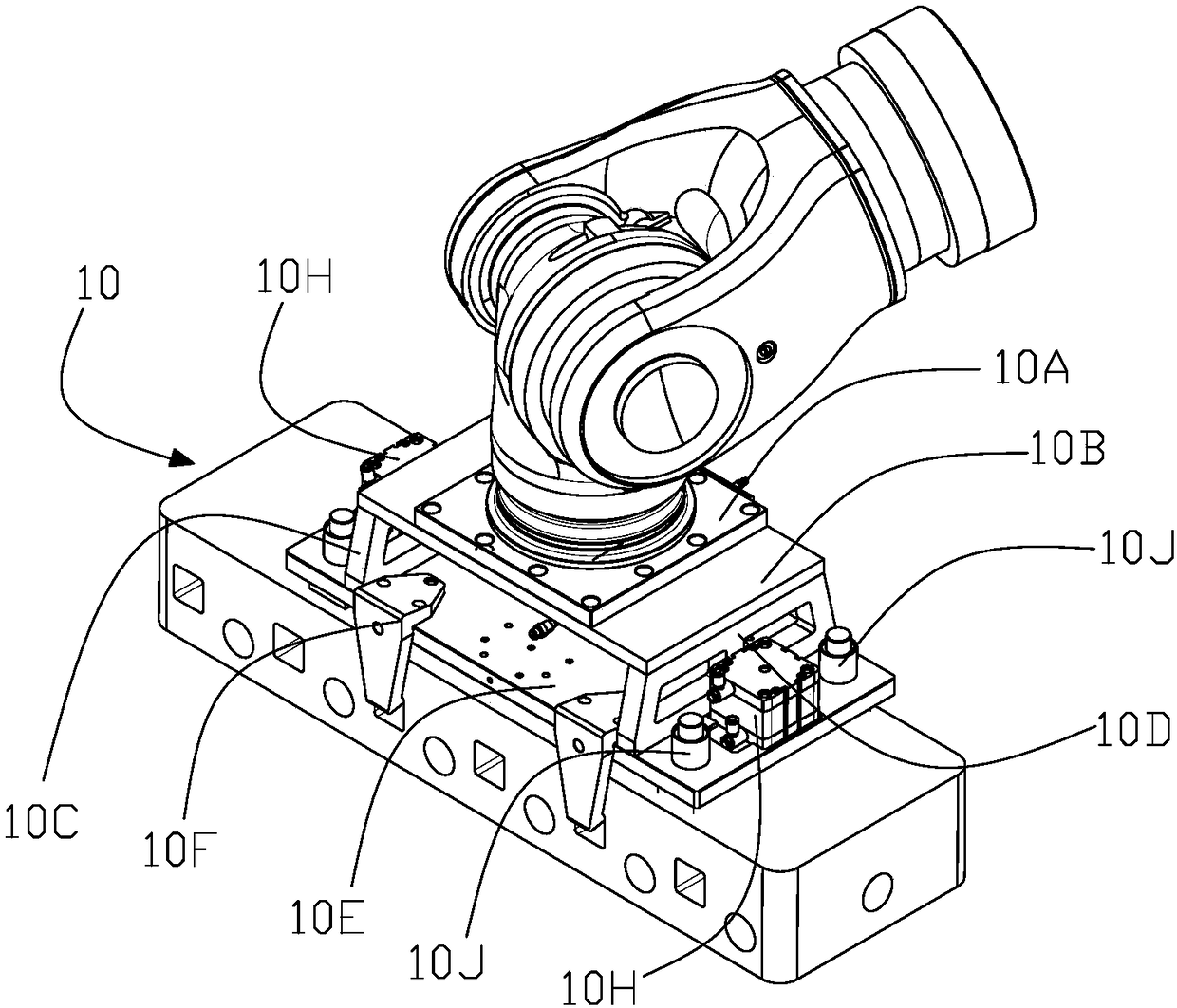
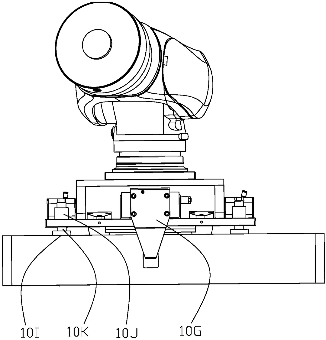
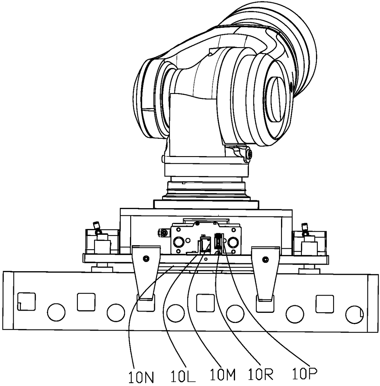
[0027] Please refer to figure 1 and figure 2 as well as image 3 As shown, this embodiment provides a vision-guided destacking engine cylinder head 10, which is installed at the end of the mechanical arm of the joint robot, including a robot mounting flange mechanism, a clamping mechanism, a pushing mechanism, a visual positioning system and a signal detection system , wherein the clamping mechanism is installed on the robot mounting flange mechanism, the pushing mechanism is arranged at both ends of the robot mounting flange mechanism, and the visual positioning system and signal detection system are located on the robot mounting flange mechanism. In the cavity of the flange mechanism, the signal detection system calculates the distance from the vision-guided engine cylinder head unstacking 10 to the engine cylinder head, and the vision positioning system finds out the position of the engine cylinder head to be transported and After inspecting the appearance, the joint rob...

Embodiment 2

[0037] Please refer to Figure 4 and Figure 5 As shown, this embodiment provides a detection robot, which includes the vision-guided engine cylinder head destacking described in Embodiment 1, and also includes a joint robot system, a visual detection and marking system 30, and a control system 40, wherein the section The robot system, the vision-guided engine cylinder head destacking 10 and the visual inspection and marking system 30 are all connected to the control system 40, and the joint robot system drives the vision-guided engine cylinder head destacking 10 to move At the upper part of the loading station to be unstacked, the control system 40 judges and calculates the position information of the workpiece to be unstacked, and sends the position information to the joint robot system, and the vision-guided engine cylinder head unstacking 10 Perform appearance inspection on the surface of the workpiece to be destacked, the joint robot system drives the vision-guided engin...


PUM


Abstract

The invention relates to a vision-guided engine cylinder head unstacking and detecting robot which comprises a robot mounting flange mechanism, a clamping mechanism, a push-on mechanism, a vision positioning system and a signal detection system, wherein the signal detection system calculates the distance of the vision-guided engine cylinder head unstacked to the engine cylinder head, the visual positioning system finds the position of the to-be-carried engine cylinder head and detects the appearance, a joint robot drives the vision-guided engine cylinder head unstacked to a grapping position and guides the clamping mechanism to clamp the engine cylinder head and the push-on mechanism to push the engine cylinder head on so as to carry the engine cylinder head to an appointed position. The robot clamps the engine cylinder head firmly, overcomes the problem that the engine cylinder head shakes in the carrying process, and avoids manual operations and improves the work efficiency effectively.

Description

technical field [0001] The invention belongs to the technical field of engine cylinder head handling, in particular to a vision-guided engine cylinder head destacking and detection robot. Background technique [0002] With the rapid development of social economy and the continuous improvement of people's living standards, my country's automobile localization process is accelerating, the demand for automobile consumption is strong, and the number of automobiles maintains a rapid growth trend, making China the world's largest automobile production and sales country. The engine cylinder head casting is the core part of the automobile engine. As the core part of the automobile engine, the engine cylinder head is also one of the most complex mass-produced castings in the automobile castings. Most of the core technologies of the engine are concentrated on the cylinder head. [0003] At present, the production and processing of engine cylinder heads mainly use manual methods for lo...

Claims


Application Information

Patent Timeline
Patent Type & Authority Applications(China)
IPC IPC(8): B25J9/00G01N21/95
CPCG01N21/95B25J9/00
Inventor 张刚
Owner 无锡黎曼机器人科技有限公司
Why Eureka
Try Eureka