[0052] Specific embodiments of the present invention will be described in more detail below with reference to the accompanying drawings. While specific embodiments of the present invention are shown in the drawings, it should be understood that the present invention may be embodied in various forms and should not be limited by the embodiments set forth herein. Rather, these embodiments are provided so that the present invention will be more thoroughly understood, and will fully convey the scope of the present invention to those skilled in the art.
[0053] It should be noted that certain terms are used in the description and claims to refer to specific components. It should be understood by those skilled in the art that the same component may be referred to by different nouns. The description and the claims do not use the difference in terms as a way to distinguish components, but use the difference in function of the components as a criterion for distinguishing. As referred to throughout the specification and claims, "comprising" or "including" is an open-ended term and should be interpreted as "including but not limited to". Subsequent descriptions in the specification are preferred embodiments for implementing the present invention, however, the descriptions are for the purpose of general principles of the specification and are not intended to limit the scope of the present invention. The scope of protection of the present invention should be determined by the appended claims.
[0054] To facilitate the understanding of the embodiments of the present invention, the following will take specific embodiments as examples for further explanation and description in conjunction with the accompanying drawings, and each accompanying drawing does not constitute a limitation to the embodiments of the present invention.
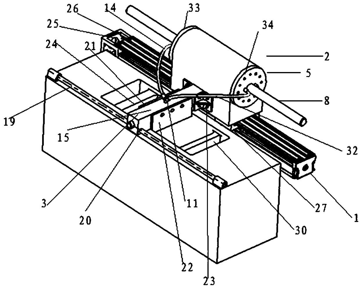
[0055] For better understanding, figure 1 It is a schematic structural diagram of a feeding device of a ceramic 3D printer according to an embodiment of the present invention, such as figure 1 As shown, a feeding device for a ceramic 3D printer includes a linear motion mechanism 1 for driving a circulating feeding cylinder, a circulating feeding cylinder 2 for continuously conveying ceramic printing materials to the scraper mechanism 3, and a continuous discharging and scraping at the same time. Scraper mechanism 3.
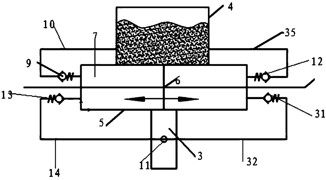
[0056] figure 2 It is a working schematic diagram of the circulating feeding cylinder of the feeding device of the ceramic 3D printer according to an embodiment of the present invention. The circulating feeding cylinder 2 includes:
[0057] hopper 4, which contains the ceramic printing material of the ceramic 3D printer,
[0058] A movable piston cylinder 5, the movable piston cylinder 5 connected to the linear motion mechanism 1 moves relative to the piston 6, and the movable piston cylinder 5 includes a piston cavity 7 for accommodating the piston 6,
[0059] Piston 6, which is sealingly arranged in said piston chamber 7 via a first sealing cover 33 and a second sealing cover 34,
[0060] A first guide rod 8, the first guide rod 8 coaxially assembled with the movable piston cylinder 5 connects the piston 6 to fix the piston 6,
[0061] One end of the first one-way valve 9 is connected to the material tank 4 via the first feeding hose 10, and the other end is connected to the upper side of the left end of the piston chamber 7,
[0062] One end of the second one-way valve 31 is connected to the manifold 11 via the first discharge hose 32, and the other end is connected to the lower side of the right end of the piston chamber 7,
[0063] The third one-way valve 12 has one end connected to the material tank 4 via the second feeding hose 35, and the other end connected to the upper side of the right end of the piston chamber 7,
[0064] The fourth check valve 13 has one end connected to the manifold 11 via the second discharge hose 14, and the other end connected to the lower left end of the piston chamber 7,
[0065] Wherein, when the movable piston cylinder 5 moves to the left relative to the piston 6, the ceramic printing material in the material box 4 enters the piston cavity 7 through the first feeding hose 10 through the first check valve 9, and enters the piston cavity 7 through the second feeding hose 10. The one-way valve 31 enters the first discharge hose 32 to reach the manifold 11 , when the movable piston cylinder 5 moves to the right relative to the piston 6 , the ceramic printing material in the tank 4 passes through the second feed hose 35 Enter the piston chamber 7 through the third one-way valve 12, and enter the second discharge hose 14 through the fourth one-way valve 13 to reach the manifold 11;
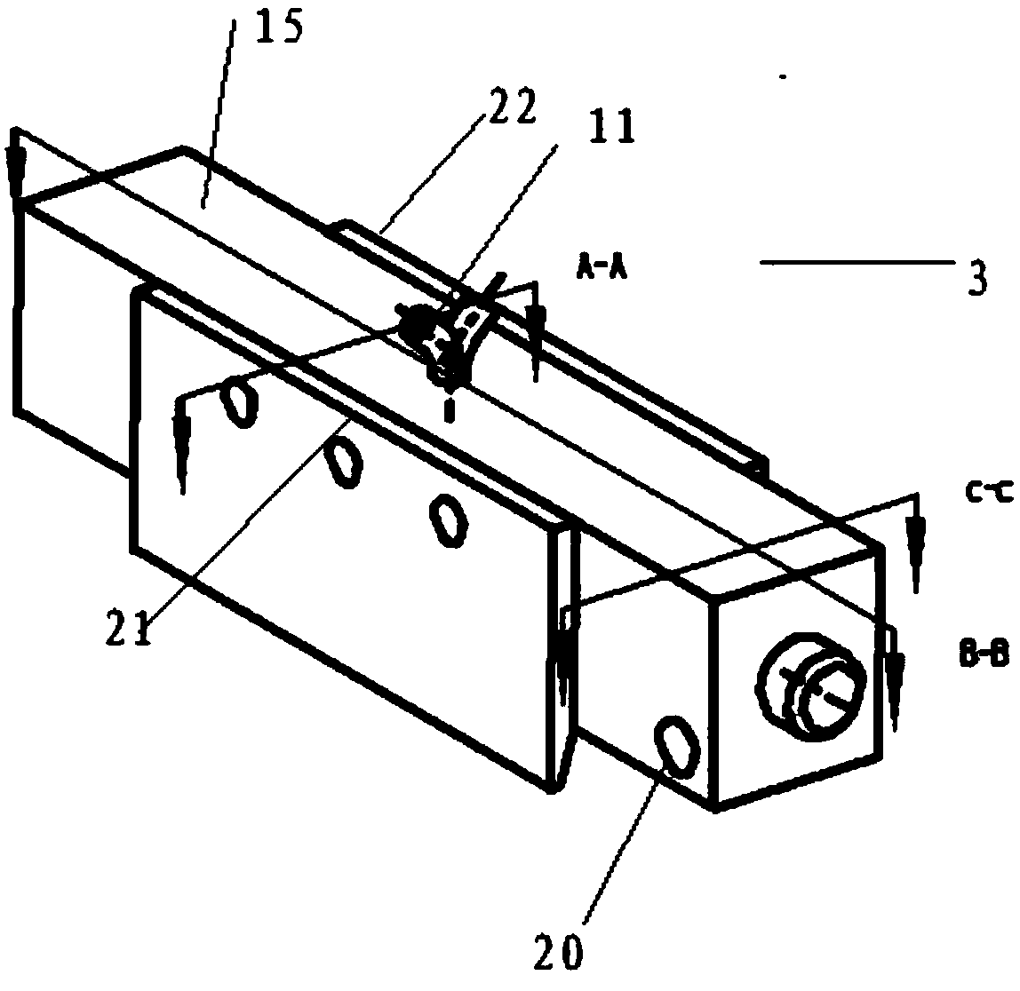
[0066] image 3 It is a schematic structural diagram of a scraper mechanism of a feeding device of a ceramic 3D printer according to an embodiment of the present invention. The scraper mechanism 3 includes:
[0067] The scraper body 15 is connected to the circulating supply cylinder 2 and moves with the movement of the movable piston cylinder 5. The scraper body 15 includes a feeding port 16 provided at the top of the scraper body 15, and accommodates the ceramic printing material from the feeding port 16. accommodating cavity 17 and a plurality of discharge ports 18 provided at the bottom end of the scraper body 15,
[0068] A collector 11, one end of the collector 11 for collecting ceramic printing materials is connected to the first and second discharge hoses, and the other end is connected to the feed port 16,
[0069] The second guide rod 19 is connected to the guide hole 20 provided on the scraper body 15 to keep the scraper body 15 moving horizontally,
[0070] The first scraper 21 and the second scraper 22 are respectively fixed on both sides of the scraper body 15 , and the bottom ends of the first scraper 21 and the second scraper 22 are respectively lower than the bottom end of the scraper body 15 by a predetermined distance.
[0071] In order to further understand the present invention, in one embodiment, the feeding device of the ceramic 3D printer is used to flatly spread the printing material of the high-viscosity plastic fluid on the working platform in preparation for subsequent curing. The feeding device of the ceramic 3D printer includes,
[0072] Circulating feeding cylinder 2: It continuously feeds the printing material to the scraper mechanism 3,
[0073] Scraper mechanism 3: Continuous discharging and scraping are carried out at the same time to prepare for subsequent curing,
[0074] Linear motion mechanism 1: Provide mechanical driving force for circulating feeding cylinder 2.
[0075] The circulating feeding cylinder 2 includes a feeding cylinder 4, a piston 6, a guide rod 8, a sealing cover, a feeding hose, a one-way valve, and a discharging hose. Among them, the guide rod 8 is connected with the piston 6, and is assembled with the material cylinder under the requirement of ensuring the coaxiality; the sealing cover is connected with two types of one-way valves; under the connection of screws, the two sealing covers are assembled with the material cylinder; The feeding hose is connected with the second one-way valve, and the feeding hose is connected with the first one-way valve; the feeding hose is connected with the material box containing the printing material, and the discharging hose is connected with the collector 11 of the scraper structure .
[0076] The scraper mechanism 3 includes a scraper, a positioning seat, a scraper seat, a collector, an overflow valve and a guide rod. The collector 11 is located in the center of the scraper body 15 and is connected to the feed port of the scraper body; the overflow valve is connected to the overflow port of the scraper body; the scraper body is assembled with the guide rod through the shaft hole, and the projected distance between the scraper mechanism and the working platform is not greater than 1mm, but not in direct contact. The scraper is fixed on the scraper body by screws, and the scraper mechanism 3 is connected with the circulating feeding cylinder 2 through the positioning seat, and its movement follows the circulating feeding cylinder 2 .
[0077] The linear motion mechanism 1 includes a stepping motor, a ball screw, and a moving slider. The linear motion mechanism is connected with the circulating feeding cylinder through the slider; the driving source adopts a stepping motor and is connected through a coupling.
[0078] Hydraulic valves are all valves suitable for non-Newtonian fluids.
[0079] In one embodiment, the feed is driven by the linear motion mechanism to drive the internal and external pressure difference generated by the relative movement of the circulating supply cylinder 2 and the piston 6. Under the action of atmospheric pressure, the printing material in the material box 4 is passed through the hose and the one-way valve. Squeeze the feeding cylinder; discharge through the linear motion mechanism 1 to drive the circulating feeding cylinder 2 to move relative to the piston, the piston pushes the printing material out of the feeding cylinder through the one-way valve, and enters the scraper mechanism through the discharge hose to realize the left chamber feeding At the same time, the right chamber is discharging, and the right chamber is feeding while the left chamber is discharging. It is worth noting that the volume of the material cylinder minus the volume occupied by the piston should be greater than or equal to the maximum printing layer thickness to ensure the printing requirements. The excess material can be scraped into the recovery tank by scraper for recovery.
[0080] In one embodiment, Image 6 It is a schematic cross-sectional view of the scraper mechanism in the C-C direction of the feeding device of the ceramic 3D printer according to an embodiment of the present invention. In order to maintain the force balance, not to tilt, and to ensure the parallelism with the forming platform, the guide rod 19 is used to match the shaft hole; the scraper body 15 is matched with the positioning seat to connect with the circulating feeding cylinder.
[0081] In one embodiment, after the scraper body 15 is connected with the supply cylinder 2, the scraper part will move with the movement of the supply cylinder, and at the same time, the printing material is continuously extruded through the piston and enters the inside of the scraper body; The material is discharged from the mouth and laid on the forming work platform; therefore, the discharging and scraping are carried out at the same time.
[0082] In a preferred embodiment of the present invention, the ceramic printing material is a high-viscosity plastic fluid material.
[0083] Figure 4 It is a schematic cross-sectional view of the scraper mechanism of the feeding device of the ceramic 3D printer in the direction A-A according to an embodiment of the present invention. In a preferred embodiment of the present invention, the feeding port 16 is located at the center of the top of the scraper body 15, Figure 5 It is a schematic cross-sectional view of the scraper mechanism of the feeding device of the ceramic 3D printer according to an embodiment of the present invention in the B-B direction.
[0084] In a preferred embodiment of the present invention, the scraper body 15 is connected to the circulating supply cylinder 2 via the positioning seat 23 , and the projected distance between the scraper body 15 and the working platform 24 for carrying the ceramic printing material is not greater than 1 mm.
[0085] In a preferred embodiment of the present invention, the linear motion mechanism 1 is a ball screw mechanism, which includes a stepping motor 25 for providing driving force, a ball screw 26 and a moving slider 27 for connecting the circulating supply cylinder 2 .
[0086] In a preferred embodiment of the present invention, the volume of the piston cavity 7 minus the volume occupied by the piston 6 is greater than or equal to the volume of the ceramic printing material required to form the maximum printing layer thickness.
[0087] In a preferred embodiment of the present invention, the scraper body 15 is provided with an overflow port 28 , and the overflow relief valve 29 is connected to the overflow port 28 . When a blockage occurs, there are other channels for the fluid to come out to prevent damage to the equipment and play an insurance role.
[0088] Figure 7 It is a working schematic diagram of the scraper mechanism of the feeding device of the ceramic 3D printer moving to the right according to an embodiment of the present invention. In a preferred embodiment of the present invention, the working platform 24 includes a recovery cylinder for accommodating the excess ceramic printing material after scraping. 30. The width of the recovery cylinder 30 is greater than or equal to the horizontal width of the first scraper 21 and the second scraper 22 so that the material can be completely scraped into the recovery cylinder. The stroke of the scraper should be consistent with the stroke of the piston to ensure the accurate coordination of the feeding and scraping.
[0089] Figure 8 It is a schematic diagram of steps of a feeding method using a feeding device of a ceramic 3D printer according to an embodiment of the present invention. The steps of a feeding method using the feeding device of a ceramic 3D printer include:
[0090] In the first step S1, when the movable piston cylinder 5 moves to the right relative to the piston 6, the ceramic printing material in the material box 4 enters the piston cavity 7 through the second feeding hose 35 through the third one-way valve 12, and Enter the second discharge hose 14 through the fourth one-way valve 13 to reach the manifold 11. The ceramic printing material enters the accommodating cavity 17 through the feeding port 16 through the manifold 11, and then is flattened on the working platform 24 through the discharging port 18. As the movable piston cylinder body 5 moves to the right, the scraper body 15 moves to the right synchronously, so that the ceramic printing material is spread on the work platform 24 through the discharge port 18 while passing through the first scraper 21 and the second scraper 22. Scrape down, and the excess ceramic printing material is collected in the recycling tank 30;
[0091] In the second step S2, when the movable piston cylinder 5 moves to the left relative to the piston 6, the ceramic printing material in the material box 4 enters the piston cavity 7 through the first feed hose 10 through the first check valve 9, and Enter the first discharge hose 32 through the second one-way valve 31 to reach the manifold 11 , the ceramic printing material enters the accommodating cavity 17 through the feeding port 16 through the manifold 11 , and then is flattened on the work platform 24 through the discharging port 18 As the movable piston cylinder 5 moves to the left, the scraper body 15 moves to the left synchronously, so that the ceramic printing material is tiled on the working platform 24 through the discharge port 18 while passing through the first scraper 21 and the second scraper 22 Scrape down, and the excess ceramic printing material is collected in the recycling tank 30;
[0092] In the third step S3, the first step and the second step are repeated to move back and forth while feeding and scraping until the end.
[0093] A ceramic 3D printer includes the feeding device.
[0094] Although the embodiments of the present invention have been described above with reference to the accompanying drawings, the present invention is not limited to the above-mentioned specific embodiments and application fields, and the above-mentioned specific embodiments are only illustrative and instructive, rather than restrictive . Those of ordinary skill in the art can also make many forms under the inspiration of this specification and without departing from the scope of protection of the claims of the present invention, which all belong to the protection of the present invention.