Electrothermal forming cold setting equipment module

A cold setting and equipment technology, applied in the field of assembly molds, can solve the problems of large air pollution and large energy loss, and achieve the effect of saving high costs, improving production efficiency and increasing production capacity

Pending Publication Date: 2018-09-18
张艳琛
View PDF0 Cites 3 Cited by
  • Summary
  • Abstract
  • Description
  • Claims
  • Application Information

AI Technical Summary

Problems solved by technology

[0002] The existing thermoforming and cold-setting equipment and supporting molds on the market need to be heated by high-temperature steam and cooled by low-temperature water (because the fluid in the cooling water pipeline is the same), and the heat energy used is all, and all of them use boilers to burn energy The heat energy generated, after burning energy (coal, biomass, oil, and natural gas will cause air pollution), heats water to become high-temperature steam, and then transmits it to the equipment through the gas transmission pressurized pipeline for use, which not only consumes energy during the transportation process The loss is large, and in the process of burning energy to generate heat, the air pollution to the environment is also large. After this invention, the electrothermoforming cold-setting equipment module can replace the original thermoforming and cold-setting equipment mold that generates serious heat pollution. And can save a lot of boiler and energy transmission pipeline construction costs, provide a pollution-free production environment

Method used


Image

  • Electrothermal forming cold setting equipment module
  • Electrothermal forming cold setting equipment module
  • Electrothermal forming cold setting equipment module

Examples


Embodiment Construction

[0019] The technical solutions in the embodiments of the present invention will be clearly and completely described below in conjunction with the accompanying drawings in the embodiments of the present invention. Obviously, the described embodiments are only some of the embodiments of the present invention, not all of them. Based on the embodiments of the present invention, all other embodiments obtained by persons of ordinary skill in the art without making creative efforts belong to the protection scope of the present invention.

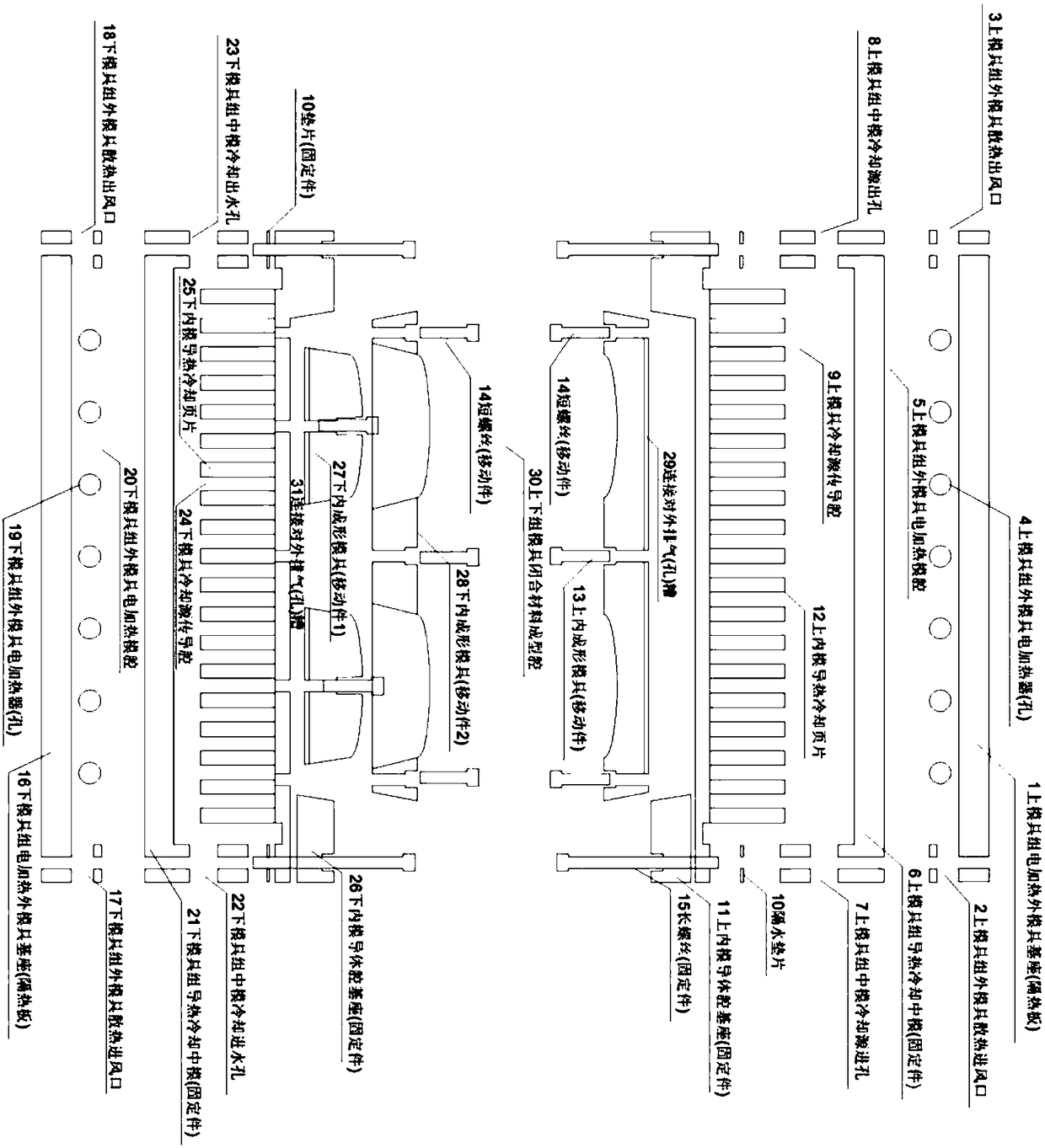
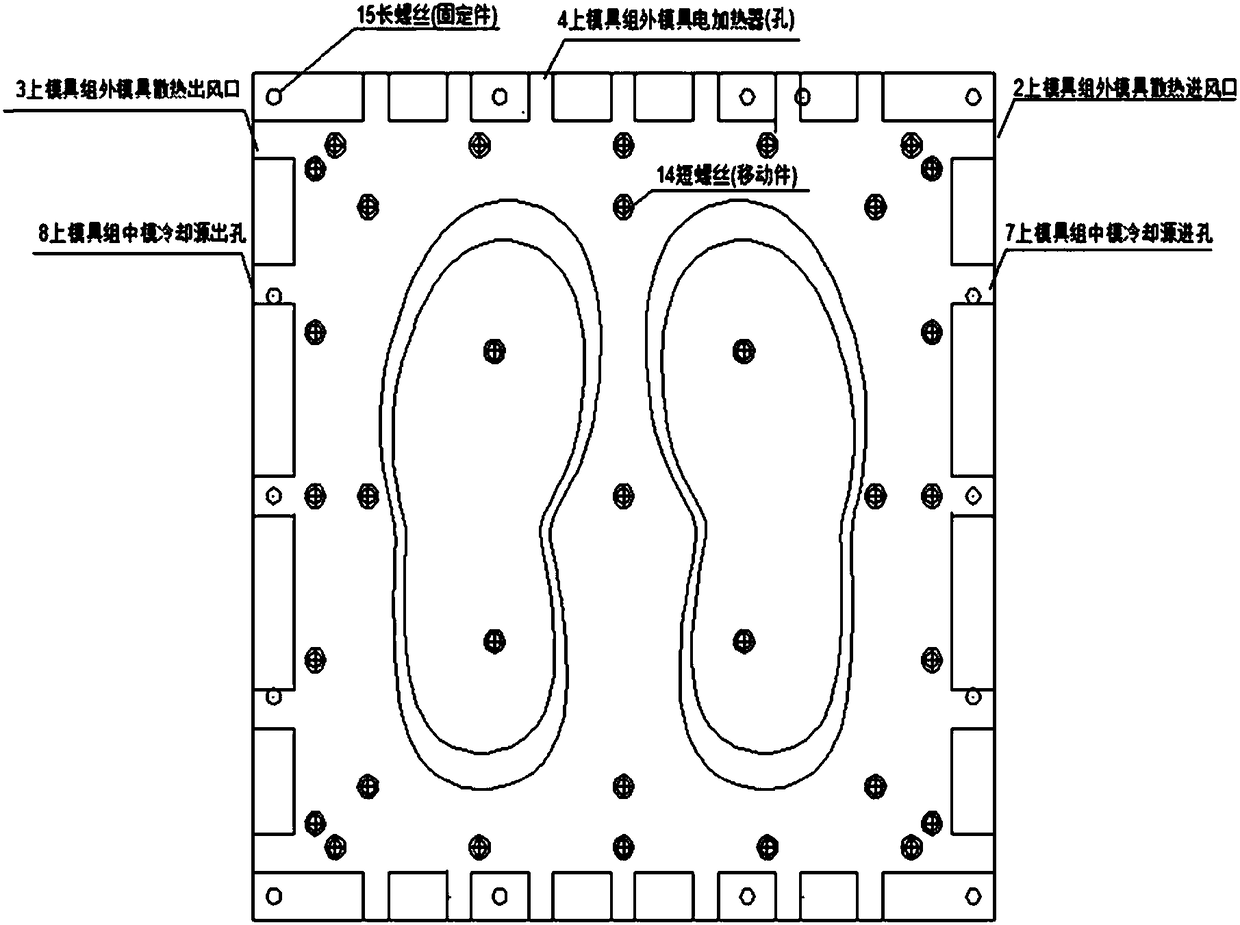
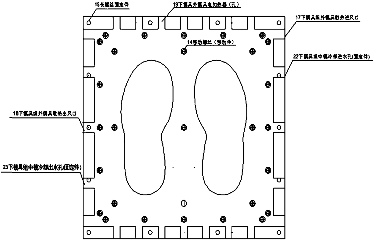
[0020] see Figure 1-4 , the present invention discloses a technical solution: the electrothermoforming cold-setting equipment module is a combined upper and lower mold group structure, and the upper mold group is (1) the upper mold group electrically heats the outer mold base (heat insulation board) and ( 6) Upper mold group heat conduction cooling middle mold (fixed part), (11) upper inner mold conductor cavity base (fixed part) (13) upper inner ...


PUM


Abstract

The invention discloses an electrothermal forming cold setting equipment module, the appearance of an assembled mold is the same as that of a common mold, and the mold is formed by working and formingupper and lower closed surfaces, the rapid electric energy heating forming cold setting assembling type mold is formed by assembling an upper mold assembly and a lower mold assembly, a closed surfaceforming material working cavity is arranged in the upper mold assembly and the lower mold assembly, the internal structures of the upper mold assembly and the lower mold assembly further respectivelycomprise an upper layer hollow working chamber and a lower layer hollow working chamber for conduction of cold and heat sources for a fluid, an upper outer mold assembly and a lower outer mold assembly are made of a thermal insulation material, a middle inner mold is made of a metal material with high heat conductivity, middle outer mold assemblies are fixed parts, after the mold is combined, a hollow cavity formed by an outer mold and a middle mold is an electric heating working cavity, a movable part of the inner mold is a production molding mold, the molding mold can be simply replaced atany time, fin-shaped sheets for absorbing heat and conducting heat cooling on the back surface of the fixing parts of the middle mold and the inner mold are used as a strengthening heat absorption surface and a heat conduction channel when in heating, and when in cooling, the fin-shaped sheets have the function of accelerating heat absorption and cooling.

Description

technical field [0001] The invention relates to an environment-friendly and energy-saving assembled mold for directly heating and forming a water-cooled shaping equipment with electric heat energy. Background technique [0002] The existing thermoforming and cold-setting equipment and supporting molds on the market need to be heated by high-temperature steam and cooled by low-temperature water (because the fluid in the cooling water pipeline is the same), and the heat energy used is all, and all of them use boilers to burn energy The heat energy generated, after burning energy (coal, biomass, oil, and natural gas will cause air pollution), heats water to become high-temperature steam, and then transmits it to the equipment through the gas transmission pressurized pipeline for use, which not only consumes energy during the transportation process The loss is large, and in the process of burning energy to generate heat, the air pollution to the environment is also large. After ...

Claims


Application Information

Patent Timeline
IPC IPC(8): B29C51/30B29C51/42
CPCB29C51/30B29C51/428
Inventor 张艳琛
Owner 张艳琛
Why Eureka
Try Eureka