Electromagnetic lock driving circuit

A driving circuit and electromagnetic lock technology, which is applied in the field of locks, can solve the problems of unlocking or locking, high energy consumption, etc., and achieve the effects of increasing safety and reliability, less energy consumption, and preventing accidental unlocking

Inactive Publication Date: 2018-09-18
CHANGXING HENGDA ELECTRONICS MATERIAL CO LTD
View PDF0 Cites 2 Cited by
  • Summary
  • Abstract
  • Description
  • Claims
  • Application Information

AI Technical Summary

Problems solved by technology

Although this method has a simple circuit structure, it needs to be connected to the power supply for both unlocking and locking, which not only consumes a lot of energy, but also cannot be realized once the power supply is cut off.

Method used


Image

  • Electromagnetic lock driving circuit
  • Electromagnetic lock driving circuit
  • Electromagnetic lock driving circuit

Examples


Embodiment Construction

[0025] The technical solutions of the present invention will be clearly and completely described below in conjunction with the accompanying drawings. Apparently, the described embodiments are some of the embodiments of the present invention, but not all of them. Based on the embodiments of the present invention, all other embodiments obtained by persons of ordinary skill in the art without making creative efforts belong to the protection scope of the present invention.

[0026] In addition, the technical features involved in the different embodiments of the present invention described below may be combined with each other as long as there is no conflict with each other.

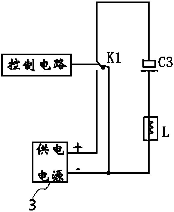
[0027] Such as figure 1 As shown, this embodiment provides an electromagnetic lock driving circuit, including a dual control switch K1, a capacitor C3, a power supply 3 and a control circuit for controlling switching of the dual control switch K1, the movable contact of the dual control switch K1 and the seco...


PUM


Abstract

The invention discloses an electromagnetic lock driving circuit, and belongs to the technical field of locks. The electromagnetic lock driving circuit comprises a dual-control switch K1, a capacitor C3, a power supply and a control circuit for controlling the dual-control switch K1 to be switched. A moving contact and a first fixed contact of the dual-control switch K1, the capacitor C3, and an excitation coil L of an electromagnetic lock form a series loop, the first fixed contact of the dual-control switch K1 is further connected with a negative electrode of the power supply, and a second fixed contact of the dual-control switch K1 is connected with a positive electrode of the power supply. The electromagnetic lock driving circuit can still be locked or unlocked when the power supply ispowered off, the structure is simple, consumed energy is less, and the reliability is high.

Description

technical field [0001] The invention relates to the technical field of locks, in particular to an electromagnetic lock drive circuit. Background technique [0002] Electromagnetic locks generally include iron pillars, springs, permanent magnets and excitation coils. The iron pillars are the moving parts of the electromagnetic lock, and are the main body of the electromagnetic lock being attracted and released. The spring provides resilience for the release of the electromagnetic lock when it is unlocked (or locked). , the positive current is passed through the exciting coil to generate a positive magnetic field, or the reverse current is passed to generate a reverse magnetic field, which cooperates with the magnetic field of the permanent magnet to realize unlocking and locking. The electromagnetic lock drive circuit is used to control the forward current and reverse current generated on the excitation coil to drive the locking and unlocking actions of the electromagnetic lo...

Claims


Application Information

Patent Timeline
Patent Type & Authority Applications(China)
IPC IPC(8): E05B47/00
CPCE05B47/0003E05B2047/0048E05B2047/005
Inventor 丁俞岚
Owner CHANGXING HENGDA ELECTRONICS MATERIAL CO LTD
Why Eureka
Try Eureka