Three-degree-of-freedom spherical hybrid magnetic bearing with axial self-loop

A technology of hybrid magnetic bearings and degrees of freedom, applied to shafts and bearings, bearings, shafts, etc., can solve the problems of limited rotor speed, gyro effect, and large volume, which is conducive to high-speed operation and easy control and analysis , the effect of reducing the volume

Active Publication Date: 2018-09-18
JIANGSU UNIV
View PDF5 Cites 2 Cited by
  • Summary
  • Abstract
  • Description
  • Claims
  • Application Information

AI Technical Summary

Problems solved by technology

[0004] The purpose of the present invention is to improve the structure of the existing three-degree-of-freedom hybrid magnetic suspension bearing, solve the problems of its excessive volume, limit the maximum speed of the rotor, and easily produce gyro effect, etc., and propose a compact structure, optimized rotor speed, integration degree, etc. Three-DOF Spherical Hybrid Magnetic Bearing with High Axial Self-loop

Method used


Image

  • Three-degree-of-freedom spherical hybrid magnetic bearing with axial self-loop
  • Three-degree-of-freedom spherical hybrid magnetic bearing with axial self-loop
  • Three-degree-of-freedom spherical hybrid magnetic bearing with axial self-loop

Examples


Embodiment Construction

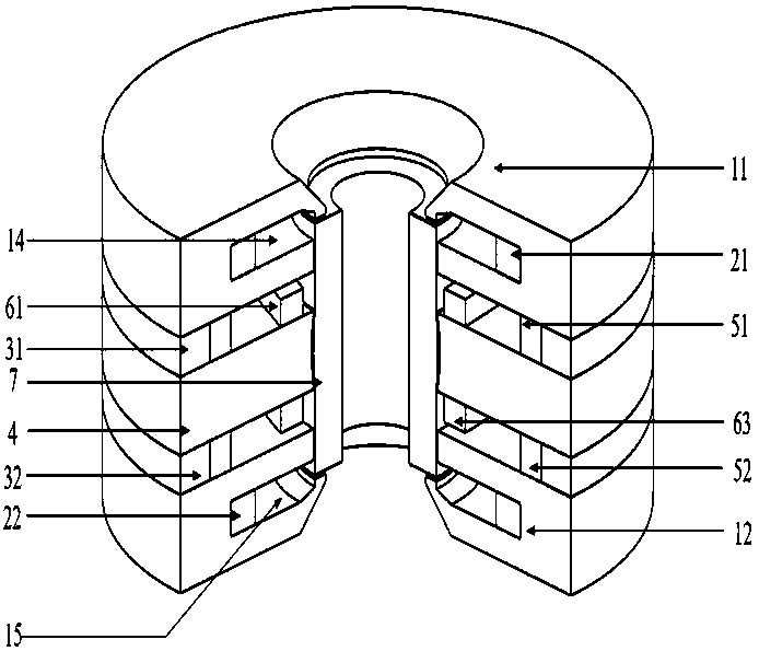
[0027] see figure 1 , the present invention as a whole is a symmetrical structure up and down in the axial direction. The rotor 7 is in the middle of the axial direction. The upper axial stator 11, the upper annular permanent magnet 31, and the radial stator are coaxially sleeved outside the rotor 7 from top to bottom. 4. The lower annular permanent magnet 32 ​​and the lower axial stator 12 . Moreover, the outer diameters of the upper axial stator 11 , the upper annular permanent magnet 31 , the radial stator 4 , the lower annular permanent magnet 32 ​​, and the lower axial stator 12 are the same. The radial stator 4 is set outside the middle of the rotor 7. The upper axial stator 11 and the lower axial stator 12 have the same structure and are symmetrically arranged up and down along the center of the rotor 7. The upper annular permanent magnet 31 and the lower annular permanent magnet 32 ​​have a complete structure. The same and arranged symmetrically up and down along the ...


PUM


Abstract

The invention discloses a three-degree-of-freedom spherical hybrid magnetic bearing with an axial self-loop. An outer axial stator, an upper annular permanent magnet, a radial stator, a lower annularpermanent magnet and a lower axial stator sequentially coaxially sleeve a rotator from top to bottom, each of the upper axial stator and the lower axial stator is formed by axially connecting an upperdisc, a middle disc and a receiving disc, the inner end surface of every upper disc extend radially inwards extends to form a conical disc, small discs are arranged between the upper and lower end surfaces of the rotor and the corresponding conical discs, the small discs are closely attached to the upper and lower surfaces of the corresponding conical discs, the upper small disc is located abovethe upper end surface of the rotor, and the lower small disc is located below the lower end surface of the rotor; and axial air gaps are left between the upper and lower small disks and the end surface of the rotor, and a control magnetic flux enters the receiving discs through return air gaps to axially form the self-loop without mounting a pushing disc, so the rotating speed of the rotor is optimized, and coupling of axial and radial magnetic fields is reduced.

Description

technical field [0001] The invention relates to a non-mechanical contact magnetic suspension bearing, in particular to a three-degree-of-freedom spherical hybrid magnetic bearing, which is suitable for the suspension support of a vehicle-mounted flywheel battery. Background technique [0002] The on-board flywheel battery uses the magnetic suspension support and the rotational inertia of the flywheel to realize energy storage. Due to the limited space of the electric vehicle, the volume requirement for the flywheel battery is relatively high. The magnetic levitation bearing is a key component supporting the flywheel battery, and its volume directly affects the volume of the flywheel battery. The axial control design of existing magnetic bearings is usually achieved by installing a thrust disc on the rotor. This design not only increases the mass of the rotor but also increases the friction and wind resistance of the rotating shaft when the flywheel battery is running at high...

Claims


Application Information

Patent Timeline
Patent Type & Authority Applications(China)
IPC IPC(8): F16C32/04
CPCF16C32/0451F16C32/0468F16C32/0485F16C2361/55F16C2380/00
Inventor 张维煜程玲
Owner JIANGSU UNIV
Why Eureka
Try Eureka