
Drying device based on swing type air guide plate

A drying device and air deflector technology, applied in drying, drying machine, drying gas arrangement, etc., can solve problems such as slow start-up speed, large energy consumption, and long warm-up time

Inactive Publication Date: 2018-09-18
扬州益洋科技发展有限公司
View PDF0 Cites 4 Cited by
  • Summary
  • Abstract
  • Description
  • Claims
  • Application Information

AI Technical Summary

Problems solved by technology

[0002] In the processing and manufacturing industry, metal parts need to be impregnated with paint. After the impregnated paint is completed, the parts need to be put into a drying device for drying operation to accelerate the curing of the paint on the surface of the parts. In order to improve the efficiency of drying work, often A larger drying device is used to meet the needs of drying a large number of parts at one time, but the large oven has high power, slow start-up speed, long warm-up time, and large energy consumption. To solve the above problems, it is necessary to A component drying device with high internal space utilization and rapid drying. In another patent application of the applicant "A drying device with adjustable partitions", in order to make the hot air flow when the partitions are inclined The air conduction performance is good, and the airflow direction is changed by segmentally controlled louvers, but each time the louvers need to be manually opened and closed, the operation is complicated, the degree of automation is low, and the air inlet angle cannot be accurately grasped

Method used


Image

  • Drying device based on swing type air guide plate
  • Drying device based on swing type air guide plate
  • Drying device based on swing type air guide plate

Examples


Embodiment Construction

[0022] The present invention will be further illustrated below in conjunction with the accompanying drawings and specific examples. The examples are implemented on the premise of the technical solutions of the present invention. It should be understood that these examples are only used to illustrate the present invention and are not intended to limit the scope of the present invention.

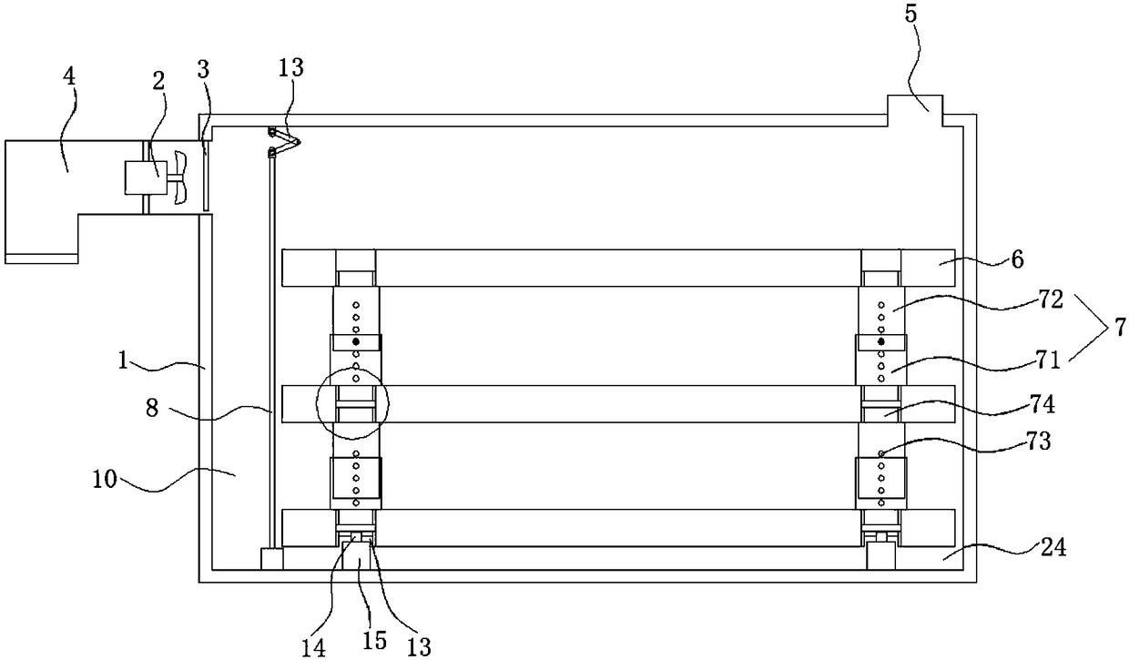
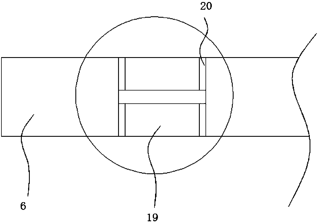
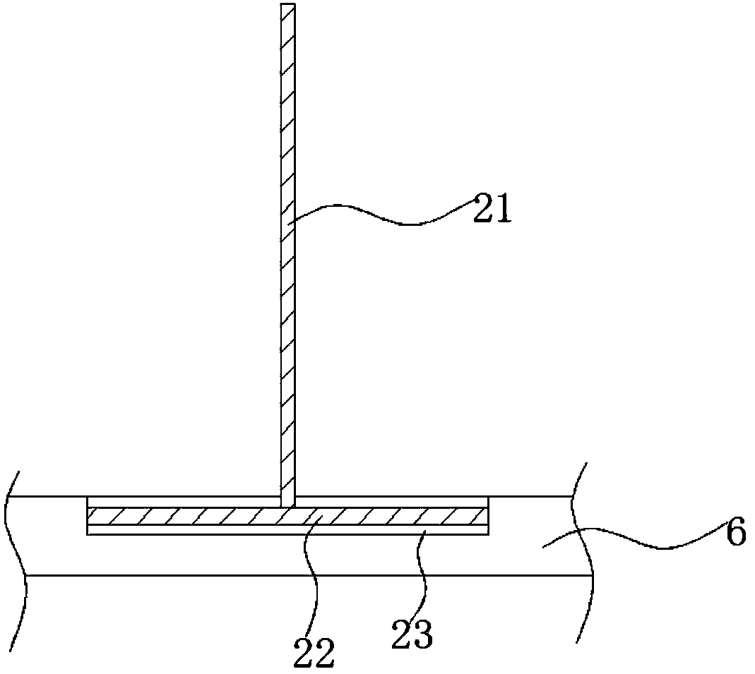
[0023] Such as Figure 1 to Figure 6 As shown, a drying device based on a swinging air deflector includes a box body 1, a fan 2, a heater 3, an air inlet 4 and an air outlet 5, and the air inlet 4 is arranged on the upper part of the side wall of the box body 1, and the The inlet of the tuyere 4 is set downward, the air outlet 5 is set on the top of the box 1 close to the other side wall of the box 1, the heater 3 is a heating resistor, and the heating resistor is located inside the fan 2, and the front side of the box 1 is also set There is a box door 24 that can open and close the box body 1...


PUM


Abstract

The invention discloses a drying device based on a swing type air guide plate. The drying device comprises a box body, a draught fan, a heater, an air inlet and an exhaust opening, wherein the air inlet and the exhaust opening are formed in the box body; multiple layers of partition boards are arranged in the box body, the upper layer partition board and the lower layer partition board are supported through adjusting columns with the adjustable height, the air guide plate is arranged at the position, on one side of the air inlet, in the box body, an air guide opening is formed in the air guideplate, a crankshaft is arranged on the lower portion of the air guide plate, and is connected with the air guide plate through a second bearing, the crankshaft is in transmission connection with a drive device, and a connecting rod mechanism is arranged between the upper surface of the air guide plate and the top wall of the box body. The air guide plate which can swing up and down is adopted, air input is uniform, through adjusting of the rotating speed of the drive device, the swing frequency of the air guide plate is changed, manual adjusting is not needed, the air inlet speed and the airflow direction are changed, and parts on the partition board are heated evenly and rapidly.

Description

technical field [0001] The invention belongs to the technical field of drying devices, and in particular relates to a drying device based on a swinging air deflector. Background technique [0002] In the processing and manufacturing industry, metal parts need to be impregnated with paint. After the impregnated paint is completed, the parts need to be put into a drying device for drying operation to accelerate the curing of the paint on the surface of the parts. In order to improve the efficiency of drying work, often A larger drying device is used to meet the needs of drying a large number of parts at one time, but the large oven has high power, slow start-up speed, long warm-up time, and large energy consumption. To solve the above problems, it is necessary to A component drying device with high internal space utilization and rapid drying. In another patent application of the applicant "A drying device with adjustable partitions", in order to make the hot air flow when the ...

Claims


Application Information

Patent Timeline
Patent Type & Authority Applications(China)
IPC IPC(8): F26B9/06F26B21/00
CPCF26B9/06F26B21/001F26B21/004
Inventor 郁丁丁
Owner 扬州益洋科技发展有限公司
Learn More