Multifunctional computer terminal apparatus

A computer terminal and multi-functional technology, which is applied in the direction of support structure installation, data center, cooling/ventilation/heating transformation, etc. It can solve the problems of terminal design not being too large, damaging the terminal, and affecting safe operation, so as to ensure space utilization efficiency, reduce misoperation, and increase discharge speed

Active Publication Date: 2018-09-18
阜阳市科技型中小企业生产力促进中心有限公司
View PDF4 Cites 3 Cited by
  • Summary
  • Abstract
  • Description
  • Claims
  • Application Information

AI Technical Summary

Problems solved by technology

[0002] With the development of science and technology and the progress of society, intelligent industries are more and more accepted by people, and automated production is also widely popularized in the manufacturing industry, and the control of braking is inseparable from computer terminal control. At present, The terminals on the production line are arranged centrally in the motor cabinet for easy arrangement and control. If a large number of terminals are placed together, a large amount of heat will be generated, which can easily cause excessive temperature and even damage the terminals. The mutual interference of adjacent terminals must be separated, which causes the design of the terminal to not be too large, otherwise it cannot be stored in the motor cabinet. At present, in order to adapt to the small installation volume in the motor cabinet, many terminals combine the screen and The control panel is designed on the same panel, which may easily cause touch-type abnormal operation and affect the safety of the device. Moreover, the design of the small keyboard and small screen may easily cause mistakes in the operation process and affect safe operation. Some designs are Design fewer terminals in the electrical cabinet, which ensures the safety of device operation, but this method results in low space utilization, wastes a lot of space, and increases costs

Method used


Image

  • Multifunctional computer terminal apparatus
  • Multifunctional computer terminal apparatus
  • Multifunctional computer terminal apparatus

Examples


Embodiment Construction

[0015] The following will clearly and completely describe the technical solutions in the embodiments of the present invention with reference to the accompanying drawings in the embodiments of the present invention. Obviously, the described embodiments are only some, not all, embodiments of the present invention. Based on the embodiments of the present invention, all other embodiments obtained by persons of ordinary skill in the art without making creative efforts belong to the protection scope of the present invention.

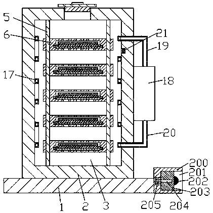
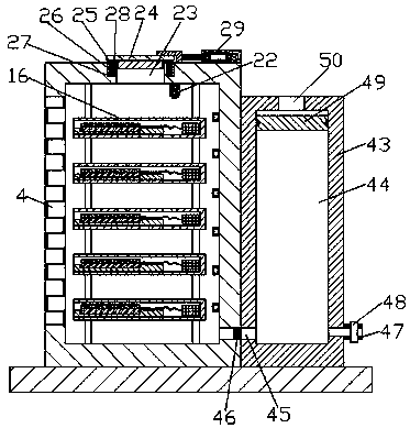
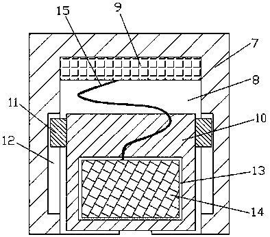
[0016] see Figure 1-4, an embodiment provided by the present invention: a multifunctional computer terminal device, including a fixed base 1, a sealed cabinet 2 is arranged on the front side of the upper end surface of the fixed base 1, and a storage space 3 is arranged inside the sealed cabinet 2 , the front end wall of the storage space 3 is provided with a sealed closed door 4, the four corners of the storage space 3 are provided with a vertical fixed rod ...


PUM


Abstract

The invention discloses a multifunctional computer terminal apparatus. The multifunctional computer terminal apparatus comprises a fixed base; a sealed machine cabinet is arranged on the front side ofthe upper end plane of the fixed base; a storage space is arranged in the sealed machine cabinet; a sealed closed door is arranged on the front end wall of the storage space; a plurality of terminalcontrol apparatuses are arranged in the storage space; heat dissipation tubes are uniformly distributed on the left and right end walls and the back end wall of the storage space; a refrigerator is fixedly arranged in the middle position of the right end plane of the sealed machine cabinet; a locking apparatus is fixedly arranged on the back side of the upper end plane of the sealed machine cabinet; and a high-pressure nitrogen box is fixedly arranged on the back side of the upper end plane of the fixed base. In operation of the multifunctional computer terminal apparatus, nitrogen enters thestorage space through air inlet holes to discharge air from the storage space, so that quick cooling and fire extinguishing can be realized; and in addition, a sealed weight-balancing block is declined along with discharging of nitrogen in the high-pressure nitrogen storage space, so that nitrogen in the high-pressure nitrogen storage space is extruded and the nitrogen discharging speed is accelerated.

Description

technical field [0001] The invention relates to the field of electronic control, in particular to a multifunctional computer terminal device. Background technique [0002] With the development of science and technology and the progress of society, intelligent industries are more and more accepted by people, and automated production is also widely popularized in the manufacturing industry, and the control of braking is inseparable from computer terminal control. At present, The terminals on the production line are arranged centrally in the motor cabinet for easy arrangement and control. If a large number of terminals are placed together, a large amount of heat will be generated, which can easily cause excessive temperature and even damage the terminals. The mutual interference of adjacent terminals must be separated, which causes the design of the terminal to not be too large, otherwise it cannot be stored in the motor cabinet. At present, in order to adapt to the small insta...

Claims


Application Information

Patent Timeline
Patent Type & Authority Applications(China)
IPC IPC(8): H05K7/14H05K7/20A62C3/16
CPCA62C3/16H05K7/1488H05K7/20709
Inventor 黄政
Owner 阜阳市科技型中小企业生产力促进中心有限公司
Why Eureka
Try Eureka