Centrifugal compressor casing with large intervals and small circumferential through holes

A technology of centrifugal compressors and large intervals, which is applied in the direction of machines/engines, mechanical equipment, liquid fuel engines, etc. It can solve the problems of increasing engine weight and cost, complex pipeline structure and control valves, and obvious influence of mainstream, so as to achieve convenience The effect of application implementation and simple structure

Active Publication Date: 2018-09-21
NANJING UNIV OF AERONAUTICS & ASTRONAUTICS
View PDF4 Cites 4 Cited by
  • Summary
  • Abstract
  • Description
  • Claims
  • Application Information

AI Technical Summary

Problems solved by technology

But its disadvantage is that the excitation intensity needs to be applied is very large, and the impact on the mainstream is obvious. While expanding the stability margin

Method used


Image

  • Centrifugal compressor casing with large intervals and small circumferential through holes
  • Centrifugal compressor casing with large intervals and small circumferential through holes
  • Centrifugal compressor casing with large intervals and small circumferential through holes

Examples


Embodiment 1

[0026] Example 1 (Take a micro turbojet engine centrifugal compressor as an example)

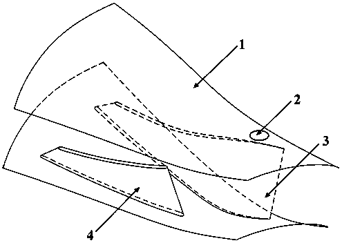
[0027] The casing of a centrifugal compressor with large circumferential intervals and small through-holes. Its structure includes casing 1, through-holes 2, main blades 3, and shunt blades 4; the through-holes 2 are provided on the surface of casing 1, main blades 3 and shunt blades 4 Set inside the receiver 1.

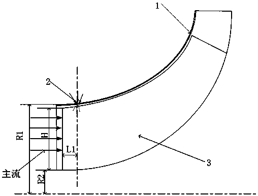
[0028] There are N1 through holes 2, which are arranged around the surface of the casing 1 at a short distance L1 between the rotor impeller inlet and the leading edge of the blade. The number of through holes 2 is selected with reference to the number of main blades of the centrifugal compressor. The number of main blades of the compressor is Z, it is known that Z=10, N1 / Z is 0.5, N1=5.

[0029] The pressure in the flow field inside the compressor at the position of the through hole is negative, and the excitation method is periodic jet action. The distance between the center of the thr...

Embodiment 2

[0032] Example 2 (Take a micro turbojet engine centrifugal compressor as an example)

[0033] The casing of a centrifugal compressor with large circumferential intervals and small through holes. Its structure includes casing 1, through holes 2, main blades 3, and shunt blades 4; the through holes 2 are provided on the surface of casing 1, main blades 3 and shunt blades 4 Set inside the receiver 1.

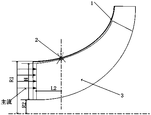
[0034] There are N1 through holes 2 which are arranged around the surface of the casing 1 at the long distance L2 between the rotor impeller inlet and the leading edge of the blade. The number of through holes 2 is selected with reference to the number of main blades of the centrifugal compressor. The number of main blades of the compressor is Z, it is known that Z=10, N1 / Z is 0.5, then N1=5.

[0035] The pressure in the flow field inside the compressor at the position of the through hole is positive, and the excitation method is periodic suction. The distance between the center of the t...


PUM


Abstract

The invention relates to a centrifugal compressor casing with large intervals and small circumferential through holes. The casing structurally comprises a casing, through holes, main blades and splitter blades, wherein the through holes are formed in the surface of the casing; the main blades and the splitter blades are arranged inside the casing; the gas flow at the through holes is driven by utilizing the relative movement of the casing and a rotor and the pressure difference between interior and exterior of the casing at the through holes; and the gas flow in the through holes periodicallysweeps through a compressor rotor flow channel to realize the periodic excitation effect on the flow in the compressor. The casing has the advantages that: (1) the influence range and the strength ofunfavorable low-energy flow near blade tips of the centrifugal compressor can be inhibited, so that the stable working margin of the centrifugal compressor is significantly expanded; (2) the influenceon the efficiency of the centrifugal compressor is small by utilizing an unsteady excitation effect; and (3) the casing is simple in structure and convenient to apply and implement.

Description

Technical field [0001] The invention relates to a casing of a centrifugal compressor with large circumferential intervals and small through holes, which belongs to the technical field of compressor design. Background technique [0002] With the requirements of modern aeroengines for high thrust-to-weight ratio, low fuel consumption, and small windward area, compressors need to have a higher stage pressure ratio to meet these performance requirements. However, the higher the stage pressure ratio of the compressor, the greater the load, and unstable conditions such as rotating stall and surge are likely to occur. Unstable working conditions such as rotating stall and surge will bring about a sharp drop in engine performance and serious vibration problems, which will adversely affect the life of the engine. Therefore, it is necessary to develop effective flow control means to expand the stability margin of the compressor. [0003] Due to the high Mach number of the blade tip flow fi...

Claims


Application Information

Patent Timeline
IPC IPC(8): F04D29/42F04D29/68
CPCF04D29/4206F04D29/682F04D29/684
Inventor 黄国平洪树立杨雨轩张志远刘泽鹏
Owner NANJING UNIV OF AERONAUTICS & ASTRONAUTICS
Why Eureka
Try Eureka