
A multifunctional hydraulic cleaning and filtering method

A filtration method and multi-functional technology, applied in the direction of fluid pressure actuating device, fluid pressure actuating system components, fluid pressure actuating system testing, etc. Solve problems such as replenishing oil, and achieve the effect of facilitating maintenance, fault diagnosis, and improving work efficiency

Active Publication Date: 2019-11-05
HANGZHOU DIANZI UNIV
View PDF1 Cites 0 Cited by
  • Summary
  • Abstract
  • Description
  • Claims
  • Application Information

AI Technical Summary

Problems solved by technology

[0003] However, the existing hydraulic oil filter car only provides the function of filtering, and cannot clean the inside of the hydraulic system
At the same time, the filtration accuracy is not as high as possible. Different equipment has different requirements for the cleanliness of the oil. An aircraft braking system has much higher requirements for the cleanliness of hydraulic oil than the hydraulic system of an excavator. The existing technology There is no way to provide multiple filter grades
Leakage problems are inevitable during the operation of the hydraulic system, and the filtration itself will also cause oil loss. The traditional hydraulic oil filtration method does not solve the problem of replenishing oil.
When a hydraulic system needs to filter and clean the hydraulic oil, it is often accompanied by maintenance and troubleshooting of the entire hydraulic system. The existing oil filtering methods cannot perform data analysis on hydraulic oil pollutants. The liquid is taken out and sent for analysis, which is very imprecise
After the filter device has been working for a period of time, it is often replaced or cleaned based on the experience of the workers, which adds a lot of uncertainty to the filter cleaning process

Method used


Image

  • A multifunctional hydraulic cleaning and filtering method

Examples


Embodiment Construction

[0030] The present invention will be further described below in conjunction with accompanying drawing.

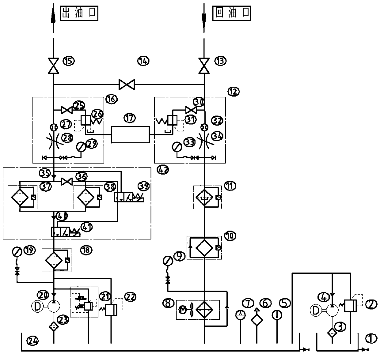
[0031] Such as figure 1 Shown, a kind of multi-function hydraulic cleaning filter method, specifically as follows:

[0032] (1) Oil return filter cleaning process

[0033]Connect the oil return port of the oil return joint with the hydraulic system that needs to be filtered. The oil passes through the oil return stop valve 13, and then successively passes through the oil return flow meter 32, the oil return throttle valve 34, the oil return pressure gauge 1 33, and the magnetic return valve. Filter 11, coarse filter 10, return oil pressure gauge two 9, radiator 8 enter main oil tank 24. The flow adjustment of the return flow process is realized by adjusting the oil return throttle valve 34 , and is observed through the oil return flow meter 32 . The output port of the oil return cut-off valve 13 is connected to the detection device through the oil return sampling stop va...


PUM


Abstract

The invention discloses a multifunctional hydraulic cleaning and filtering method. An existing hydraulic oil filtering method can not provide multiple filtering accuracy classes and can not carry outdata analysis on hydraulic oil pollutants. The multifunctional hydraulic cleaning and filtering method comprises the following steps that oil passes through an oil return detection opening, a magneticfilter and a coarse filter during oil return; the oil passes through an oil outlet detection opening, an adjustable filtering accuracy circuit, a fine filter and a main oil tank oil absorption filter, and the adjustable filtering accuracy circuit has three filtering accuracies for choice; a detection device which is connected with the oil return detection opening and the oil outlet detection opening provides an on-line detection function, and when the values of the pollutants reaches the preset values in the different filtering accuracies, an alarming device alarms automatically; and when theoil is required to be supplemented, the oil in an oil storage tank enters a main oil tank through an oil storage tank oil absorption filter and an oil storage tank oil pump sequentially. Free switchon the three different filtering classes is provided, and the field adaptability is high.

Description

technical field [0001] The invention relates to a hydraulic cleaning and filtering method, in particular to a multifunctional hydraulic cleaning and filtering method for engineering machinery. Background technique [0002] As an important part of the hydraulic transmission system, the quality of hydraulic oil directly affects the normal operation of the hydraulic system. About 70% of hydraulic system failures are caused by hydraulic oil. After long-term use of hydraulic oil, pollution problems will inevitably occur, resulting in varying degrees of decline in important properties such as viscosity, corrosion resistance, and lubricity. In order to maintain the normal operation of the equipment, only the method of regularly changing the hydraulic oil is adopted. This method will not only waste a lot of manpower and financial resources, but also pollute the hydraulic system during the oil change process. In order to solve this problem, some oil filter vehicles have also appear...

Claims


Application Information

Patent Timeline
Patent Type & Authority Patents(China)
IPC IPC(8): F15B21/041F15B19/00
CPCF15B19/00F15B21/041
Inventor 王志强傅祺毋少峰倪敬
Owner HANGZHOU DIANZI UNIV
Learn More