A free piston buffer mechanism

A technology of buffer mechanism and piston, applied in the field of buffer mechanism, can solve problems such as collision, and achieve the effect of improving safety, compact structure and stable buffer effect

Active Publication Date: 2020-05-12
CHINA ACAD OF AEROSPACE AERODYNAMICS
View PDF6 Cites 0 Cited by
  • Summary
  • Abstract
  • Description
  • Claims
  • Application Information

AI Technical Summary

Problems solved by technology

However, when the free piston running at high speed moves to the end of the compression tube, it often has a relatively high speed, which will cause a direct collision under the high pressure at the end of the compression tube.

Method used


Image

  • A free piston buffer mechanism
  • A free piston buffer mechanism
  • A free piston buffer mechanism

Examples


Embodiment Construction

[0028] The present invention will be described in further detail below in conjunction with the accompanying drawings and specific implementation.

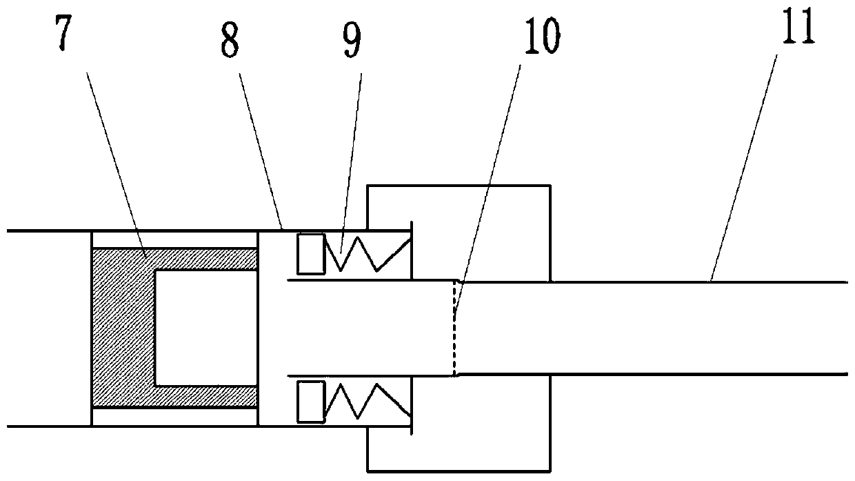
[0029] to combine image 3 , the wind tunnel body includes a compression tube 8 and a shock tube 11, and the diaphragm 10 is held between the compression tube 8 and the shock tube 11 by a clamping mechanism. The free piston 7 is set in the compression tube 8 and can move freely in the axial direction to the end of the compression tube 8. If there is still a high speed at the end of the compression tube 8, the free piston 7 will directly collide with the clamping mechanism of the diaphragm 10 , resulting in damage. Therefore, the present invention increases the free piston buffer mechanism 9, which is arranged at the tail section of the compression tube 8 and the front part of the diaphragm 10 clamping mechanism.

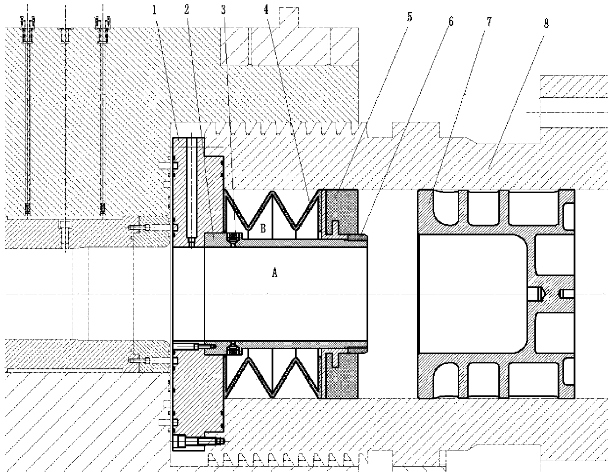
[0030] to combine figure 1 , the free piston buffer mechanism, which is suitable for buffering the impact of the end...


PUM


Abstract

The invention relates to a free piston buffer mechanism comprising an installing baseplate, an internal sleeve, a one-way valve, a spring, a buffer rubber slide block and a tail end limiting ring. Theinstalling baseplate is installed on the tail end of a wind tunnel compression pipe and used for locating and installing other buffer mechanism components. The free piston collides the free piston buffer mechanism and then the rubber slide block moves backward and the spring is compressed to provide buffer force, and the B cavity is reduced, the pressure in the B cavity is increased and the gas in the B cavity provides the buffer force. High-speed effective free piston buffering for the tail end can be realized in the free piston shock tunnel, and the influence of the pressure change of the cavity of the tail end of the compression pipe on the buffer effect can be eliminated so that the structure is compact and the operation safety of the wind tunnel can be enhanced.

Description

technical field [0001] The invention relates to a free-piston buffer mechanism, which is applied in a free-piston shock tunnel where the high-speed impact of the end of a free piston needs to be buffered, and belongs to the field of buffer mechanisms. Background technique [0002] In the free piston shock wave wind tunnel, the free piston running at high speed in the compression tube is the core component of the driving section of the wind tunnel, which is used for forward compression to generate high temperature and high pressure gas that meets the test requirements. However, when the free piston running at high speed moves to the end of the compression tube, it often has a higher speed, so that it will directly collide under the higher pressure at the end of the compression tube. If the speed of the piston is insufficient when it reaches the end of the compression tube for the first time, it will rebound under the high pressure at the front end of the piston. After rebound...

Claims


Application Information

Patent Timeline
Patent Type & Authority Patents(China)
IPC IPC(8): G01M9/04
CPCG01M9/04
Inventor 李辰陈星王玉东宋可清马雁捷谌君谋张冰冰
Owner CHINA ACAD OF AEROSPACE AERODYNAMICS
Why Eureka
Try Eureka