Multifunctional mini-tiller
A micro-tiller and multi-functional technology, applied in the direction of agricultural machinery and tools, shovel, fertilizer and seeding equipment, etc., can solve the problems of affecting work efficiency, time-consuming and labor-intensive dismantling, waste of resources, etc., to achieve simplified operation, simple and light structure, The effect of prolonging the service life
- Summary
- Abstract
- Description
- Claims
- Application Information
AI Technical Summary
Problems solved by technology
Method used
Image
Examples
Embodiment 1
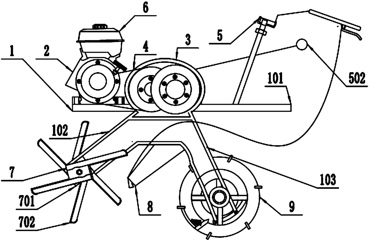
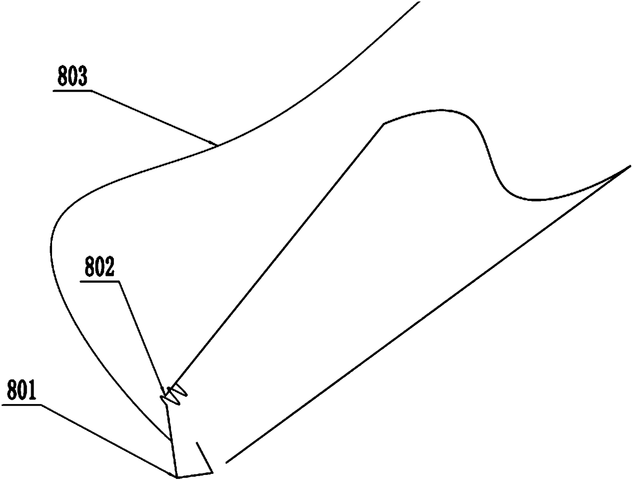
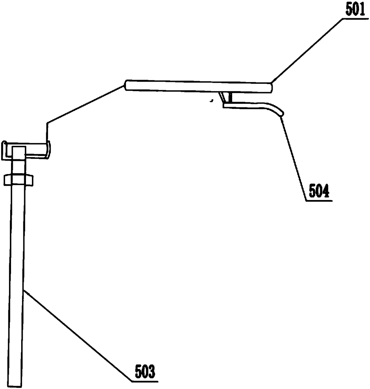
[0032] Embodiment one is basically as attached figure 1 Shown: the multifunctional micro tillage machine includes a "not" shaped frame 1, the frame 1 includes a horizontal support platform 101, a left cantilever 102 and a right cantilever 103 welded at the bottom of the horizontal support platform 101, and the frame 1 above the horizontal support platform 101 From left to right, an engine 2, a speed changer 3 and an operating assembly 5 are screwed in sequence, a toothed belt 4 is connected between the engine 2 and the speed changer 3, and an oil tank 6 filled with fuel is connected above the engine 2; Connected with rotary tiller assembly 7, fertilizer box 8 and driving sowing assembly 9 to the right. Rotary blade assembly 7 comprises blade spline shaft, blade roller 701 and blade 702, blade roller 701 is connected left cantilever 102 by blade spline shaft, blade 702 surrounds the The central axis is distributed circumferentially.
[0033] as attached figure 2 As shown: t...
Embodiment 2
[0043] as attached Figure 5 As shown: the difference between this embodiment and the first embodiment is that the kneading assembly includes an armrest cover 1001, and the armrest cover 1001 wraps the handle 501. The handle 501 is a hollow rod-shaped structure, and there is a number one travel port 1002 on the top of the handle 501 from left to right. and No. 2 travel port 1003, there are No. 3 travel port 1004 and No. 4 travel port 1005 which are staggered with No. 1 travel port 1002 and No. 2 travel port 1003 from left to right under the handle 501. The position of all the stroke ports is provided with secondary stroke ports, and a horizontal straight rod 1006 passes through the middle of the handle 501, and a vertical rod 1009 is connected between the horizontal straight rod 1006 and the inner wall of the handle 501, and the horizontal straight rod 1006 is welded from left to right. The first limit assembly 1007 and the second limit assembly 1008, the first limit assembly ...
Embodiment 3
[0049] as attached Figure 4 Shown: the difference between the present embodiment and the first embodiment is that the surface of the outer rim and the inner rim are extended with bumps 909 .
[0050] The specific implementation process is as follows: when the operator pushes the tiller forward, the ground rolling surface of the rolling field wheel becomes a bump 909. At this time, the wall of the rim 903 is not in contact with the ground, which avoids the rolling of the rim 903 when it is moving forward or backward. The seeds sprinkled into the cultivated land, because the wall of the rim 903 has a certain height from the ground, the seeds are scattered from the rim 903 and perform a parabolic motion, so the seeds are distributed more evenly after being scattered, the sowing area is improved, and the consumption of seeds is reduced.
PUM
 Abstract
Description
Claims
Application Information
 - R&D
- Intellectual Property
- Life Sciences
- Materials
- Tech Scout
- Unparalleled Data Quality
- Higher Quality Content
- 60% Fewer Hallucinations
Browse by: Latest US Patents, China's latest patents, Technical Efficacy Thesaurus, Application Domain, Technology Topic, Popular Technical Reports.
© 2025 PatSnap. All rights reserved.Legal|Privacy policy|Modern Slavery Act Transparency Statement|Sitemap|About US| Contact US: help@patsnap.com


