Centrifugal atomizing device

A technology of centrifugal atomization and centrifugal atomization disc, which is applied in the direction of spraying device, spraying device with movable outlet, etc., can solve the problems of limiting the size of atomized particles in the atomizing disc, breaking the atomizing disc, and limiting the rotation speed of the atomizing disc. , to achieve the effect of uniform irrigation and spraying, easier penetration, reduction of average particle size, and saving of liquid dosage.

Pending Publication Date: 2018-09-25
SUZHOU EAVISION ROBOTIC TECH CO LTD
View PDF10 Cites 10 Cited by
  • Summary
  • Abstract
  • Description
  • Claims
  • Application Information

AI Technical Summary

Problems solved by technology

However, for the existing centrifugal atomizing disc, it is actually impossible to achieve the ideal high speed. On the one hand, high speed will inevitably require a very large power. On the other hand, if the rotating speed reaches a certain level, the atomizing disc will be directly broken due to vibration. , so, due to the power and its own vibration, the rotation speed of the atomization disc is limited, and the size of the atomized particles of the atomization disc is also limited, which affects the spraying effect and causes a certain waste of liquid medicine
[0004] Due to the limitation of the rotation speed of the existing atomization device, the average particle size of the droplets is generally above 80 microns, and the droplets are not uniform, so the atomization effect cannot meet the operation requirements. How to improve the fog without considering the rotation speed? The atomization effect, especially the atomization effect of the average particle size of the droplets with uniform droplets below 30 microns, is the problem to be solved by this program

Method used


Image

  • Centrifugal atomizing device
  • Centrifugal atomizing device
  • Centrifugal atomizing device

Examples


Embodiment 1

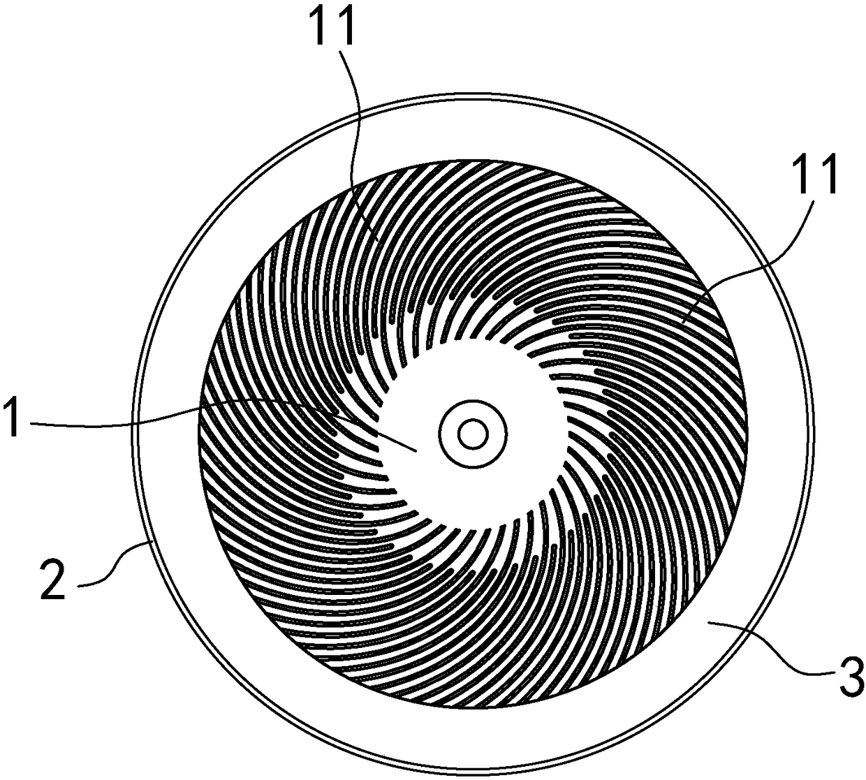
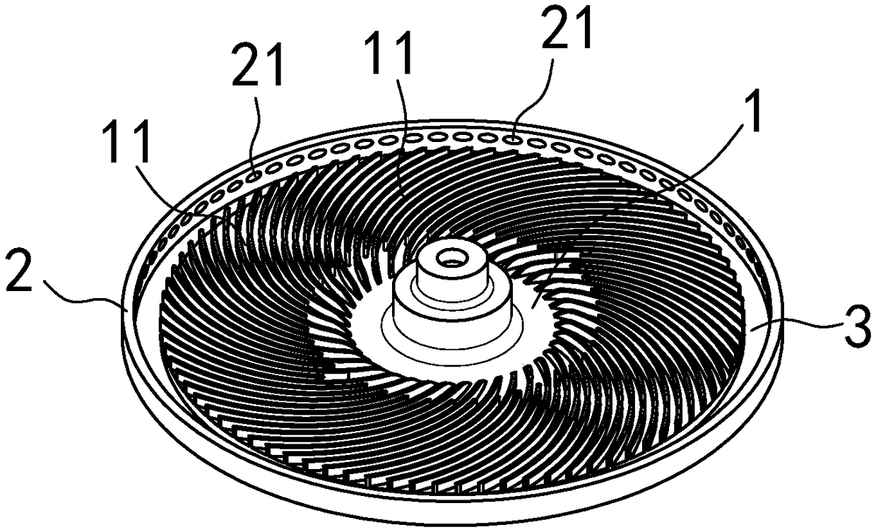
[0042] A centrifugal atomization device, set on a spraying device (handheld spraying device or spraying drone, etc.) A plurality of diversion grooves 11 are provided on the top, and each diversion groove 11 extends from the central position of the centrifugal atomizing disk 1 to the edge.

[0043] An annular body 2 is arranged on the outside of the centrifugal atomizing disc 1, and the annular body 2 is coaxial with the centrifugal atomizing disc 1 and is set in relative rotation, wherein, the centrifugal atomizing disc 1 is opposite to the spraying equipment The main body of the centrifugal atomizing disc 1 is rotated by a motor, and the annular body 2 is fixedly arranged relative to the main body of the spraying equipment, and there is a gap between the annular body 2 and the centrifugal atomizing disc 1 in its radial direction. A spacing of 3.

[0044] The annular body 2 is provided with a circle of air guide grooves along its circumference, and the inner peripheral surface ...

Embodiment 2

[0058] A centrifugal atomization device, which is set on a spraying device (handheld spraying device or spraying drone, etc.) Flow grooves 11, each flow guide groove 11 extends from the central position of the centrifugal atomizing disk 1 to the edge.

[0059] An annular body 2 is arranged on the outside of the centrifugal atomizing disc 1, the centrifugal atomizing disc 1 is rotated relative to the main body of the spraying equipment, and the annular body 2 is also rotated relative to the main body of the spraying equipment, and the centrifugal atomization The disc 1 and the annular body 2 are respectively driven and rotated by their corresponding motors. The annular body 2 is coaxial with the centrifugal atomizing disc 1 and rotates in opposite directions, and the annular body 2 and the centrifugal atomizing disc There is a distance 3 between the disks 1 in their radial direction;

[0060] The centrifugal atomizing disk 1 rotates to form a positive wind field around it, and...


PUM


Abstract

The invention discloses a centrifugal atomizing device which comprises a centrifugal atomizing disc, wherein multiple diversion trenches are formed in the centrifugal atomizing disc. The centrifugal atomizing device is characterized in that a ring body is arranged on the outer side of the centrifugal atomizing disc; the ring body and the centrifugal atomizing disc are coaxial with each other and are rotationally arranged relative to each other; a spacing is formed between the ring body and the centrifugal atomizing disc in a radial direction; the centrifugal atomizing disc rotates at the periphery to form a positive wind field; the positive wind field rotates clockwise and anticlockwise around the center of the centrifugal atomizing disc; the ring body provides a reverse wind field betweenthe ring body and the centrifugal atomizing disc in an operating state; and the reverse wind field weakens or reverses the positive wind field, so that an accelerated wind zone is formed between thecentrifugal atomizing disc and the ring body. Therefore, the relative velocity of liquid drops and air is increased, and the aim of multiplying the atomizing effect is achieved.

Description

technical field [0001] The invention relates to a centrifugal atomization device, which can be used in a spraying device, including a hand-held spraying device and a drone for spraying. Background technique [0002] Atomization is the act of dispersing a liquid into tiny droplets through a nozzle or with a high-velocity air stream. A large number of dispersed liquid droplets that are atomized can float in the air to increase the contact area with the sprayed object and improve the spraying effect. The methods of liquid atomization include pressure atomization, gas atomization, centrifugal force atomization, and sonic atomization. It means that the liquid is turned into small droplets through a special device and sprayed out in the form of mist. [0003] Centrifugal force atomization means that the atomizing disc rotates at high speed under the action of the motor. Due to the action of centrifugal force, the liquid stretches into a thin film on the surface of the rotating a...

Claims


Application Information

Patent Timeline
Patent Type & Authority Applications(China)
IPC IPC(8): B05B3/10
CPCB05B3/1021B05B3/105
Inventor 董雪松刘厚臣
Owner SUZHOU EAVISION ROBOTIC TECH CO LTD
Why Eureka
Try Eureka