Giant magnetostictive ultrasonic spindle

A technology of giant magnetostriction and giant magnetostrictive rods, which is applied in the direction of large fixed members, metal processing machinery parts, metal processing equipment, etc., can solve problems such as heat generation, and achieve the effect of solving heat generation and improving power transmission efficiency

Active Publication Date: 2018-09-25
XIAN UNIV OF TECH
View PDF6 Cites 13 Cited by
  • Summary
  • Abstract
  • Description
  • Claims
  • Application Information

AI Technical Summary

Problems solved by technology

[0005] The purpose of the present invention is to provide a giant magnetostrictive ultrasonic spindle, which solves the heating problem existing in the existing giant magnetostrictive transducers

Method used


Image

  • Giant magnetostictive ultrasonic spindle
  • Giant magnetostictive ultrasonic spindle
  • Giant magnetostictive ultrasonic spindle

Examples


Embodiment Construction

[0022] The present invention will be described in detail below in conjunction with the accompanying drawings and specific embodiments.

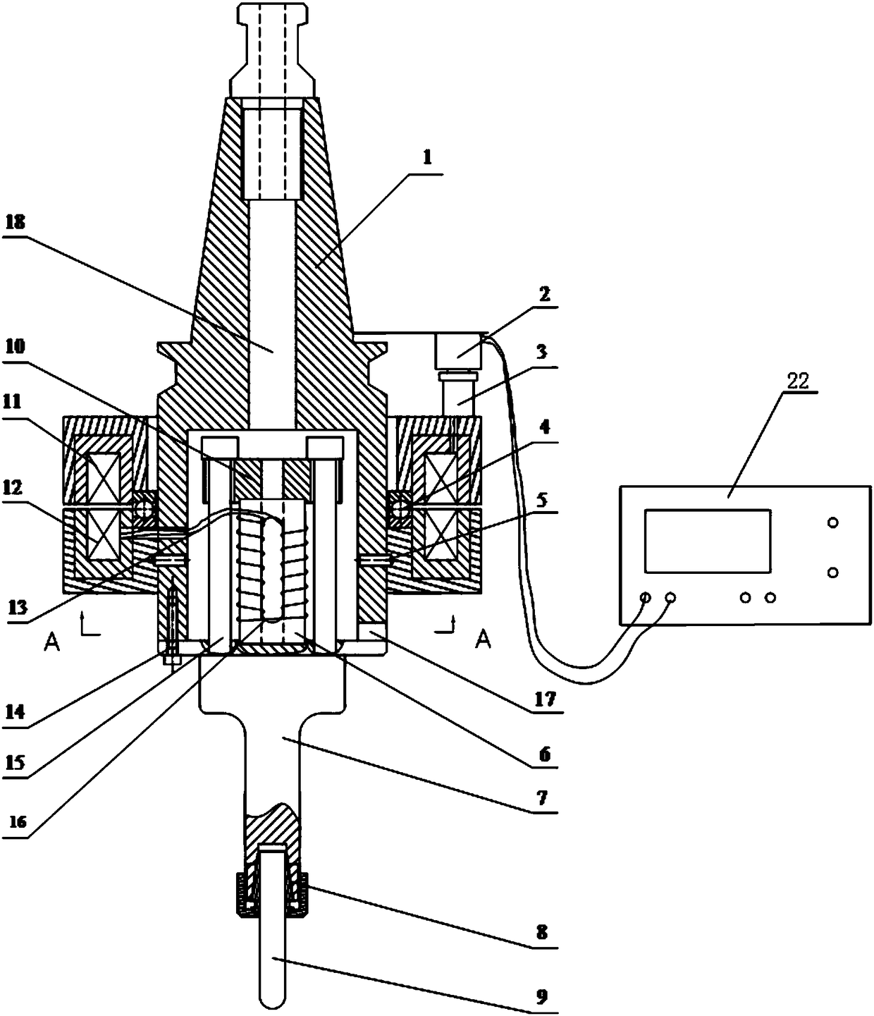
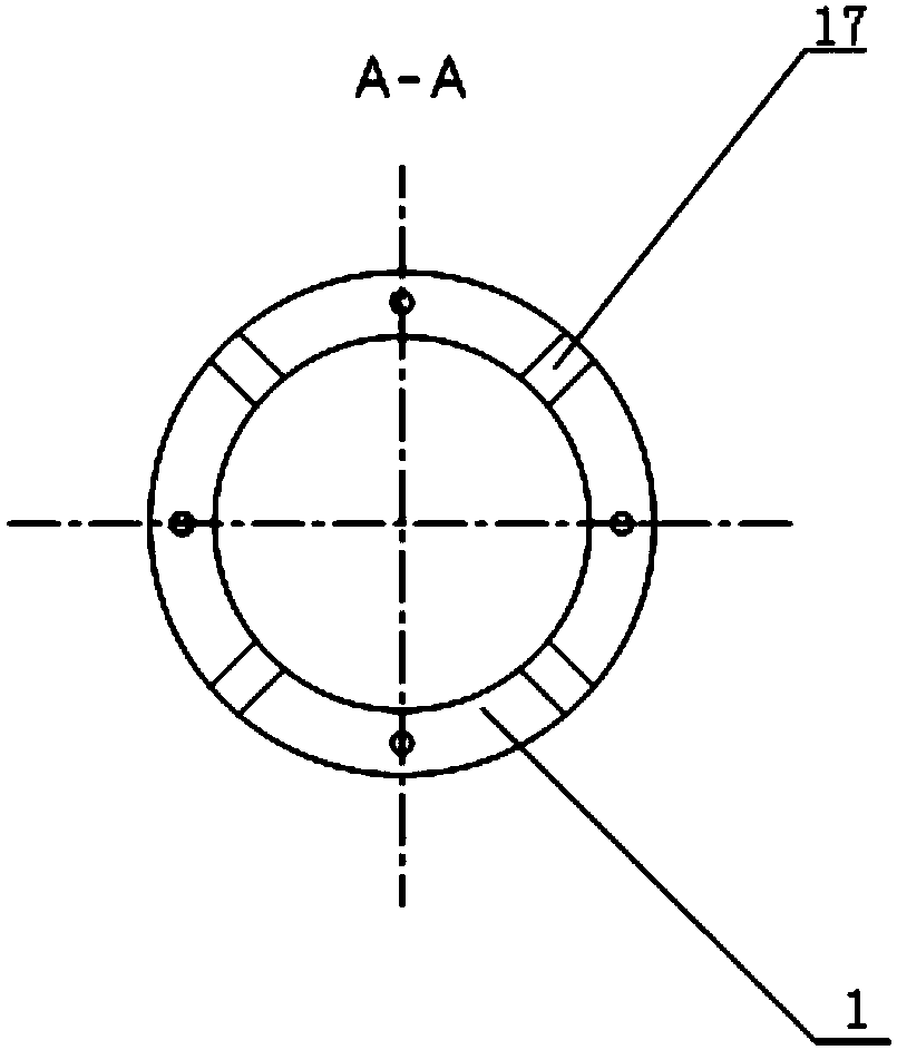
[0023] The giant magnetostrictive ultrasonic spindle of the present invention, such as figure 1 As shown, including the handle 1, the handle 1 is provided with a through hole a18 axially, and the lower end of the handle 1 is also provided with an air outlet 17, and the distribution of the air outlet 17 is as follows figure 2 As shown, the lower part of the knife handle 1 has an accommodating cavity, and the accommodating cavity communicates with the through hole a18 and the air outlet 17. A back cover 10 is arranged in the accommodating cavity, and there is a gap between the back cover 10 and the knife handle. gap, the rear cover 10 is connected to the horn 7 through the pre-tightening bolt 15, the upper end of the horn 7 is connected to the lower end of the handle 1, and the lower end of the horn 7 is connected to the tool head 9. Such as ...


PUM


Abstract

The invention discloses a giant magnetostictive ultrasonic spindle which comprises a stem, wherein a secondary winding is fixed by the stem through a screw a; electric energy is conducted to the secondary winding from a primary winding; a bearing is arranged between the secondary winding and the primary winding; a positioning pin is arranged on the primary winding; a positioning block is insertedinto the positioning pin; the positioning block is connected with an ultrasonic wave generator through a lead; the center of a giant magnetostictive telescopic rod is hollowed, is subjected to axial slicing treatment and is further stuck by using an epoxy resin; in addition, a stripy hole is communicated with a through hole c; the lead is wound on the giant magnetostictive telescopic rod; direct current is overlapped in an excitation coil to provide an offset magnetic field; a rear cover plate, the giant magnetostictive telescopic rod and an amplitude variable rod are fastened through pre-tightening bolts; the stem is connected with the amplitude variable rod through a screw b; the amplitude variable rod is connected with a tool head through an elastic clamp; a gap is formed between the stem and the rear cover plate. By adopting the giant magnetostictive ultrasonic spindle, the problem that a giant magnetostictive ultrasonic transducer radiates heat in practical processing can be effectively solved.

Description

technical field [0001] The invention belongs to the technical field of ultrasonic processing, and in particular relates to a giant magnetostrictive ultrasonic spindle. Background technique [0002] At present, in the field of ultrasonic machining technology, piezoelectric ceramics are widely used as excitation materials for ultrasonic transducers. Due to their low power density and small amplitude, overheating under high power conditions is likely to cause failure, which limits its application. Giant magnetostrictive materials have the advantages of large magnetostrictive strain, high energy density, and fast response speed, and are the research direction of high power and large amplitude. [0003] In terms of the design of giant magnetostrictive transducers, the commonly used method is to arrange magnetically permeable materials outside the coil, but because there is a certain gap in the magnetic circuit, a large magnetic flux leakage will be generated, which greatly reduce...

Claims


Application Information

Patent Timeline
Patent Type & Authority Applications(China)
IPC IPC(8): B06B1/08B23B19/02
CPCB06B1/08B23Q1/70
Inventor 李鹏阳刘强许光耀
Owner XIAN UNIV OF TECH
Why Eureka
Try Eureka