Drive control device

A drive wheel, independent drive technology, applied in the direction of control devices, power devices, electrical devices, etc.

Inactive Publication Date: 2018-09-25
NTN CORP
View PDF10 Cites 1 Cited by
  • Summary
  • Abstract
  • Description
  • Claims
  • Application Information

AI Technical Summary

Problems solved by technology

In the invention described in Patent Document 1, when the temperature of the lubricating oil or the temperature of the motor falls below a threshold value, the output limiting mechanism limits the output power of the motor.

Method used


Image

  • Drive control device
  • Drive control device
  • Drive control device

Examples


Embodiment Construction

[0039] and Figure 1 to Figure 6 Embodiments of the present invention will be described together.

[0040]

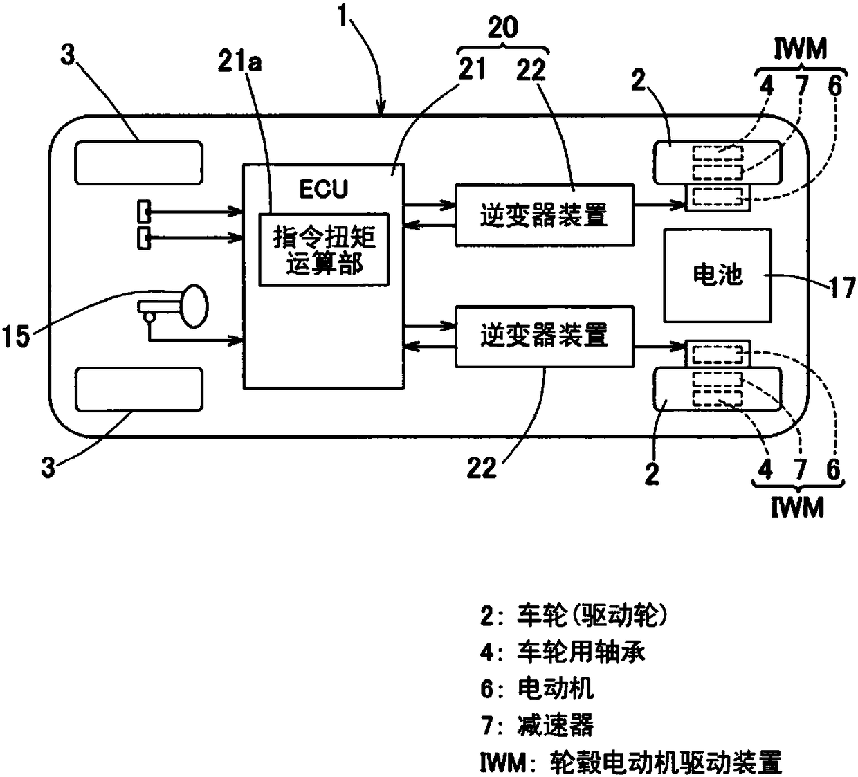
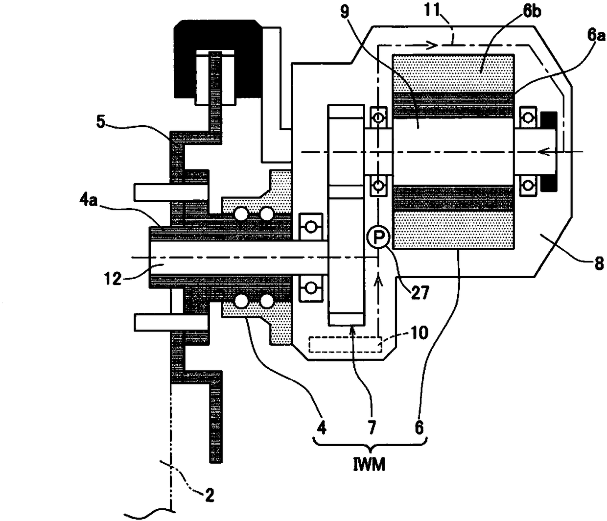
[0041] figure 1It is a block diagram showing the conceptual structure of the electric vehicle equipped with the drive control apparatus of this embodiment in plan view. This electric vehicle is a four-wheeled vehicle in which wheels 2, 2 serving as left and right rear wheels of a vehicle body 1 are drive wheels, and wheels 3, 3 serving as left and right front wheels are serving as driven wheels. Front-wheel 3,3 is made as steering wheel. The left and right drive wheels 2 , 2 are driven by independent traveling electric motors 6 . Each electric motor 6 constitutes an in-wheel motor drive device IWM which will be described later. Brakes not shown in the figure are provided on the respective wheels 2 and 3 . In addition, the left and right front wheels 3, 3 can be steered by a steering mechanism not shown, and can be steered by a steering mechanism 15 such as a hand...


PUM


Abstract

Provided is a drive control device capable of reducing the load on a speed reducer, etc., during low temperatures and capable of ensuring both minimum acceleration performance and climbing performance. This drive control device (20) controls a vehicle drive motor (6) of a vehicle comprising: the motor (6); a speed reducer (7) that decelerates the rotation of the motor (6) and transmits same to a wheel; and an oil supply mechanism that supplies lubricating oil to the motor (6) and the speed reducer (7). The drive control device (20) comprises: an oil temperature acquisition means (Sa) that obtains the temperature of the lubricating oil; and a rotation speed detection means (28) that detects the rotation speed of the motor (6). The drive control device (20) also comprises a torque limiting means (26) that limits the torque generated by the motor 6, when the oil temperature obtained by the oil temperature acquisition means (Sa) is no more than a prescribed temperature, on the basis of: the oil temperature obtained by the oil temperature acquisition means (Sa); and the rotation speed of the motor (6) detected by the rotation speed detection means (28).

Description

[0001] Associate application [0002] This application claims the priority of Japanese Patent Application No. 2017-046153 filed on March 10, 2017, the entirety of which is incorporated as a part of this application by reference. technical field [0003] The present invention relates to a drive control device capable of reducing the load on mechanical elements such as bearings and / or gears and performing necessary torque limitation at low temperatures. Background technique [0004] An in-wheel motor driving device has been proposed including an electric motor, a wheel bearing, and a speed reducer (Patent Document 1). The speed reducer described in Patent Document 1 is lubricated by lubricating oil pumped by an oil pump. In the invention described in Patent Document 1, when the temperature of the lubricating oil or the temperature of the electric motor falls below a threshold value, the output limiting mechanism limits the output of the electric motor. [0005] prior art lit...

Claims


Application Information

Patent Timeline
Patent Type & Authority Applications(China)
IPC IPC(8): B60L15/20
CPCB60L15/20B60L2240/421B60L2240/423B60L3/00B60L9/18Y02T10/72B60K7/0007B60K11/02B60K17/046B60L3/0061B60W10/30B60W50/038B60W2510/083B60W2710/081B60W2710/083
Inventor 神田刚志
Owner NTN CORP
Why Eureka
Try Eureka