Industrial sewage treatment device

A treatment device and industrial sewage technology, applied in water/sewage treatment, biological water/sewage treatment, heating water/sewage treatment, etc., can solve the problem that impurities are easily condensed and adsorbed on the inner wall of the box, sewage purification is not complete, and ecological damage is caused balance and other issues, to achieve the effect of simple structure, preventing secondary pollution, and thorough filtration

Inactive Publication Date: 2018-09-25
周圣兰
View PDF0 Cites 5 Cited by
  • Summary
  • Abstract
  • Description
  • Claims
  • Application Information

AI Technical Summary

Problems solved by technology

[0002] At present, with the rapid development of urbanization, more and more environmental pollution sources are released into the environment, but the equipment for treating these environmental pollution sources is developing slowly. The existing industrial sewage treatment equipment concentrates the sewage and discharges it directly. There are a lot of impurities in these sewage, and the pH is unbalanced. Therefore, the discharge of these sewage into the nature will cause great pollution to the environment and destroy the natural ecological balance. Especially in recent years, with the flow of urban population The burden of urban industrial sewage treatment equipment is getting heavier and heavier. The sewage tank in industrial sewage treatment equipment is used for a long time, and the impurities in the sewage are easy to condense and adsorb on the inner wall of the box, making the sewage purification not thorough

Method used


Image

  • Industrial sewage treatment device
  • Industrial sewage treatment device
  • Industrial sewage treatment device

Examples


Embodiment Construction

[0015] The following will clearly and completely describe the technical solutions in the embodiments of the present invention with reference to the accompanying drawings in the embodiments of the present invention. Obviously, the described embodiments are only some, not all, embodiments of the present invention. Based on the embodiments of the present invention, all other embodiments obtained by persons of ordinary skill in the art without making creative efforts belong to the protection scope of the present invention.

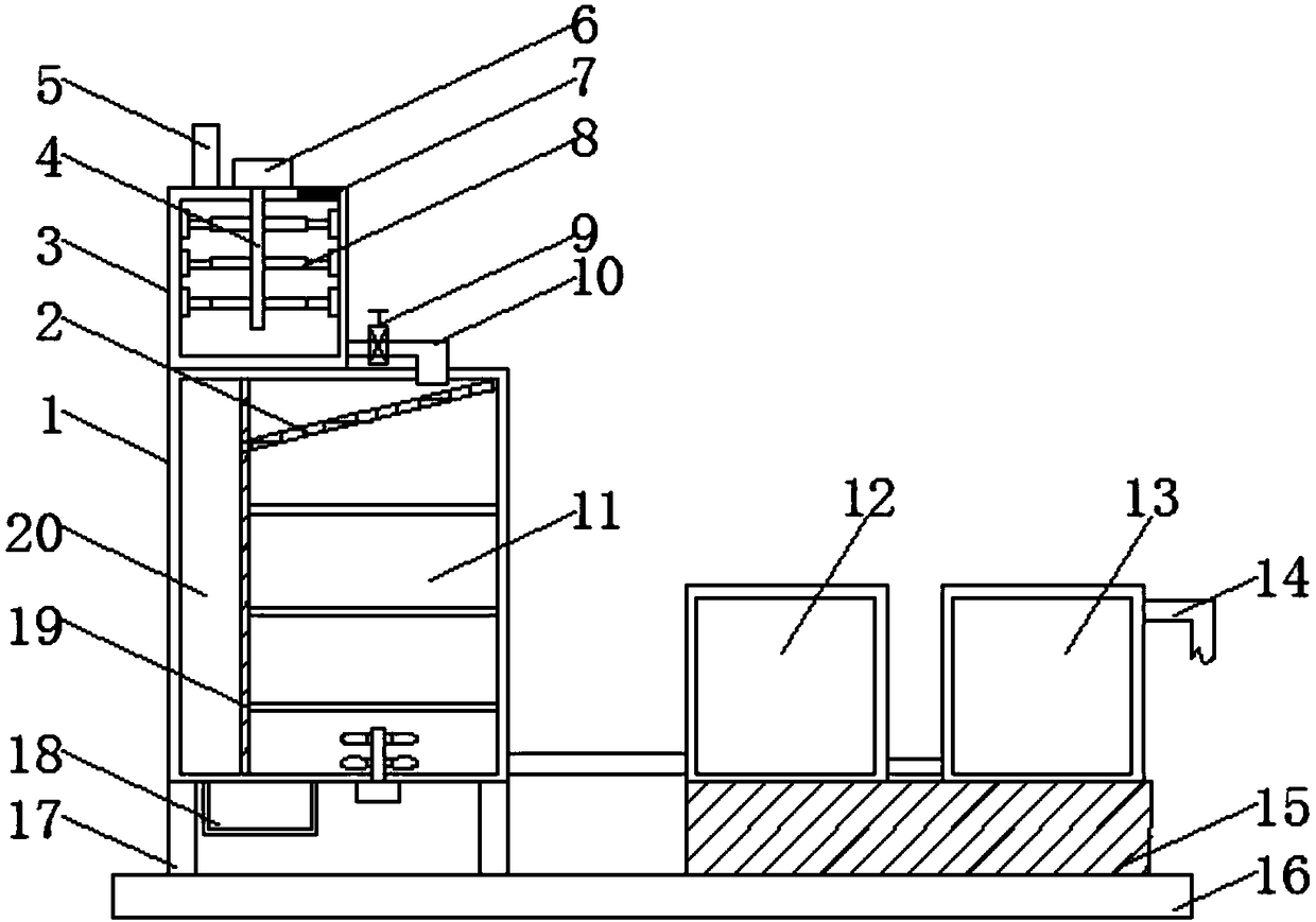
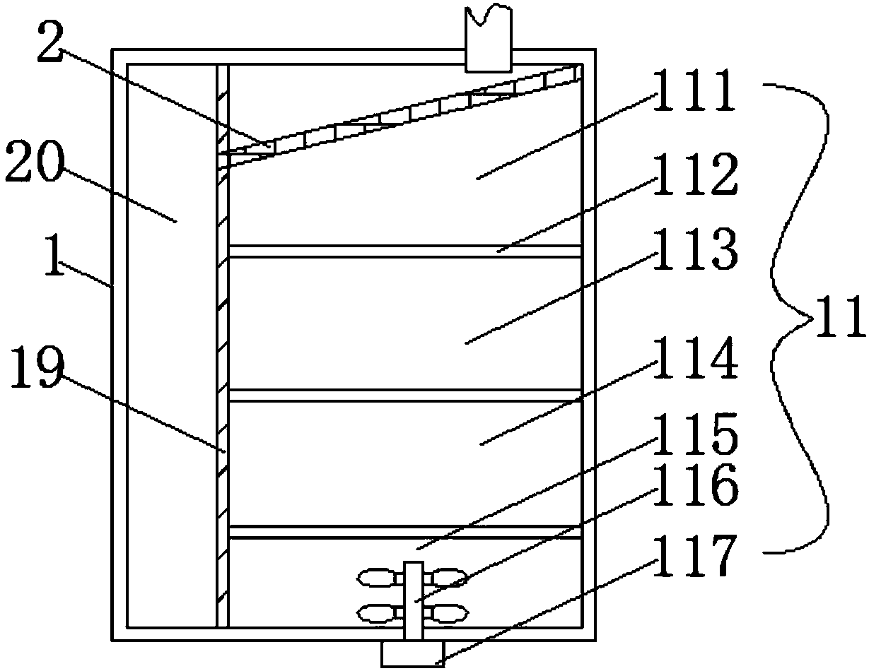
[0016] see Figure 1-4 , the present invention provides a technical solution: an industrial sewage treatment device, including a bottom plate 16, two sets of support rods 17 are arranged on the left side of the top of the bottom plate 16, a filter box 1 is arranged on the top of the two sets of support bars 17, and the inner cavity of the filter box 1 A partition 19 is vertically arranged, and the two ends of the partition 19 are respectively connected to the ...


PUM


Abstract

The invention discloses an industrial sewage treatment device and relates to the technical field of industrial environmental protection. The industrial sewage treatment device comprises a bottom plate; a filtering box is arranged at the tops of two groups of supporting rods; a separation plate is arranged in an inner cavity of the filtering box; the separation plate is used for separating the inner cavity of the filtering box into a solid box and a liquid box; a stirring box is arranged at the left side of the top of the filtering box; a water outlet pipe is arranged at the bottom of an outerwall at the right side of the stirring box; a supporting block is arranged at the right side of the top of the bottom plate; an electrolysis box is arranged at the left side of the top of the supporting block; a distillation box is arranged at the right side of the top of the supporting block; a water discharging pipe is arranged at the top of the right side of the distillation box. The device issimple in structure; a stirring device adopts a design including a sliding groove, a sliding block and a scraping sheet, so that a condition that a sedimentation substance is condensed on an inner wall of a stirring box to cause blocking so that the sedimentation efficiency is reduced is avoided; large-particle objects precipitated in sewage are separated through a solid-liquid separation net, thesolid box and the liquid box and enter an impurity groove, so that the device is prevented from being blocked and secondary pollution to water is prevented.

Description

technical field [0001] The invention relates to the technical field of industrial environmental protection, in particular to an industrial sewage treatment device. Background technique [0002] At present, with the rapid development of urbanization, more and more environmental pollution sources are released into the environment, but the equipment for treating these environmental pollution sources is developing slowly. The existing industrial sewage treatment equipment concentrates the sewage and discharges it directly. There are a lot of impurities in these sewage, and the pH is unbalanced. Therefore, the discharge of these sewage into the nature will cause great pollution to the environment and destroy the natural ecological balance. Especially in recent years, with the flow of urban population The burden of urban industrial sewage treatment equipment is also getting heavier. The sewage tank in industrial sewage treatment equipment is used for a long time, and the impuritie...

Claims


Application Information

Patent Timeline
Patent Type & Authority Applications(China)
IPC IPC(8): C02F9/14C02F101/30
CPCC02F9/00C02F1/001C02F1/04C02F1/283C02F1/46104C02F1/5281C02F3/301C02F3/308C02F2101/30C02F2303/02
Inventor 周圣兰
Owner 周圣兰
Why Eureka
Try Eureka