High-efficiency air cooler applied to heat exchanger

A high-efficiency heat exchanger technology, applied in lighting and heating equipment, steam/steam condenser, etc., can solve the problems of no protective measures, low work efficiency, inconvenient use, etc., to avoid blockage, convenient operation, The effect of easy maintenance

Inactive Publication Date: 2020-05-19
大冶市志成孔板有限公司
View PDF1 Cites 0 Cited by
  • Summary
  • Abstract
  • Description
  • Claims
  • Application Information

AI Technical Summary

Problems solved by technology

[0002] In the prior art: the patent of authorized publication number CN 208012399U discloses an air cooler, including: the air cooler body, the first flow channel, the first end of the first flow channel communicates with the inlet of the air cooler body, the first flow channel of the first flow channel The two ends are used to communicate with the liquid storage tank, the booster mechanism, the booster mechanism has a booster inlet and a booster outlet, the booster inlet is connected with the liquid storage tank, the booster outlet is connected with the inlet of the air cooler body, and the booster The pressure mechanism is used to pressurize the fluid medium that supplies liquid to the air cooler body. Its structure is complex, inconvenient to operate, and inconvenient to use. The fan is not equipped with protective measures. The external dust attached to the fan blades will increase its failure rate and troublesome maintenance. , low work efficiency

Method used


Image

  • High-efficiency air cooler applied to heat exchanger
  • High-efficiency air cooler applied to heat exchanger
  • High-efficiency air cooler applied to heat exchanger

Examples


Embodiment Construction

[0013] The technical solutions in the embodiments of the present invention will be clearly and completely described below in conjunction with the accompanying drawings in the embodiments of the present invention. Obviously, the described embodiments are only a part of the embodiments of the present invention, rather than all the embodiments. Based on the embodiments of the present invention, all other embodiments obtained by those of ordinary skill in the art without creative work shall fall within the protection scope of the present invention.

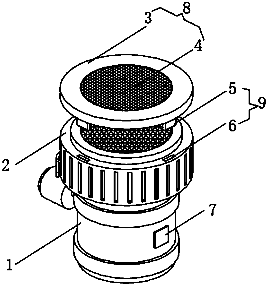
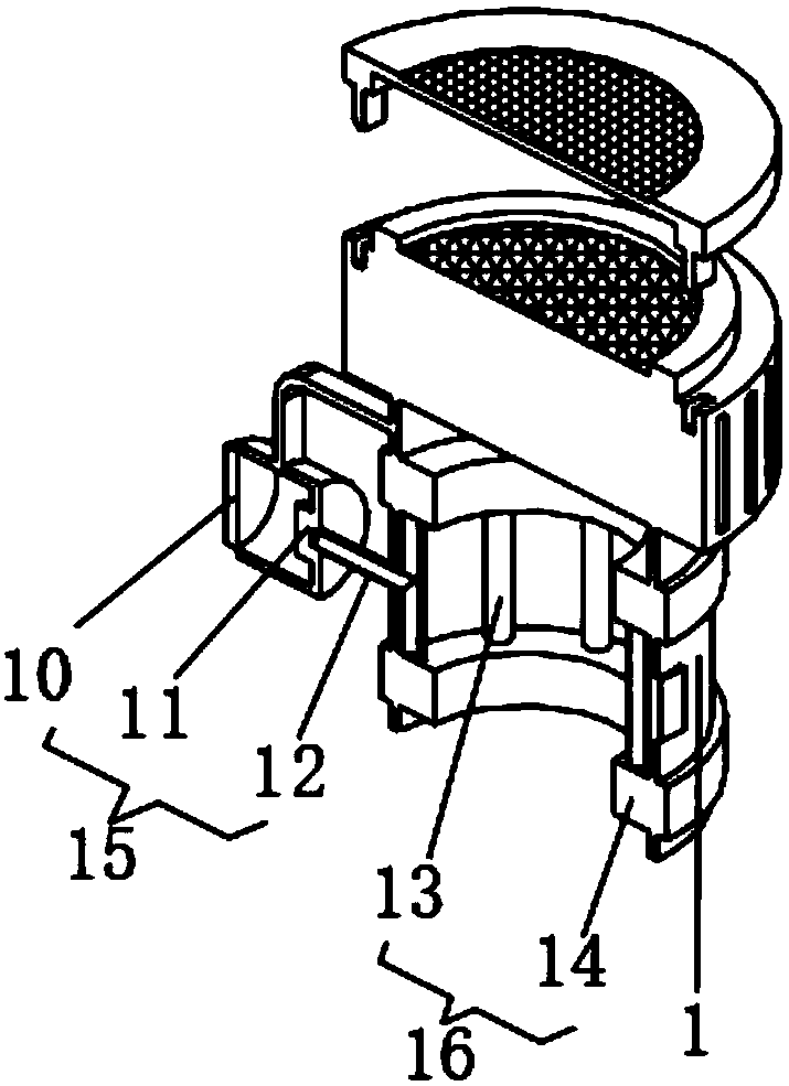
[0014] See Figure 1-2 , The present invention provides a technical solution: a high-efficiency air cooler for heat exchangers, comprising a box body 1, a ventilator 2 is installed on the top of the box body 1, and the air inlet position of the ventilator 2 is connected with a protective device through a clamping structure 9 Dust device 8, a refrigeration device 16 is installed inside the box 1, an antifreeze adding device 15 is connecte...


PUM


Abstract

The invention discloses a high-efficiency air cooler applied to a heat exchanger. The high-efficiency air cooler comprises a box body, wherein a ventilation machine is installed on the top of the boxbody; a dustproof device is connected by a clamping joint structure at an air inlet of the ventilation machine; a refrigeration device is installed on the inner side of the box body; an anti-freezingagent adding device communicates with the refrigeration device; a control switch set is installed on a side face of the box body; and an input end of the control switch set is electrically connected to an output end of an external power source. The high-efficiency air cooler applied to the heat exchanger has the beneficial effects that a dustproof mesh is used for preventing external dust from falling onto fan blades of the ventilation fan and thus influencing normal work of the ventilation machine, so the ventilation machine can work with a high efficiency, a failure rate of the ventilation machine is reduced, and maintenance cost is reduced; and an installation frame and the ventilation machine are assembled by the clamping joint structure, and the structure can be installed and dismounted easily, so the dustproof mesh can be maintained easily, dust can be prevented from accumulating on the dustproof mesh and thus influencing air inlet efficiency of the ventilation machine, and rationality of design is ensured.

Description

Technical field [0001] The invention relates to the technical field of air coolers, in particular to a high-efficiency air cooler for heat exchangers. Background technique [0002] In the prior art: a patent with authorized publication number CN 208012399U discloses an air cooler, which includes: an air cooler body, a first flow channel, the first end of the first flow channel is connected with the inlet of the air cooler body, and the first flow channel The two ends are used to communicate with the liquid storage tank. The boosting mechanism has a boosting inlet and a boosting outlet. The boosting inlet is connected to the liquid storage tank, and the boosting outlet is connected to the inlet of the air cooler body. The pressure mechanism is used to pressurize the fluid medium supplied to the air cooler body. Its structure is complex, inconvenient to operate, and inconvenient to use. The fan is not equipped with protective measures. The adhesion of external dust on the fan blade...

Claims


Application Information

Patent Timeline
Patent Type & Authority Applications(China)
IPC IPC(8): F28B1/02F28B9/00
CPCF28B1/02F28B9/00
Inventor 汪莹
Owner 大冶市志成孔板有限公司
Why Eureka
Try Eureka