Multidirectional coordination type rotary one-way movable bridge support

A bridge support and coordinated technology, applied in bridges, bridge parts, bridge construction, etc., can solve problems such as aggravated friction pair damage speed, complex stress state, and jamming

Pending Publication Date: 2018-09-25
GUIZHOU TRANSPORTATION PLANNING SURVEY & DESIGN ACADEME
View PDF0 Cites 2 Cited by
  • Summary
  • Abstract
  • Description
  • Claims
  • Application Information

AI Technical Summary

Problems solved by technology

In terms of load, the horizontal force of conventional one-way movable spherical bearings generally does not exceed 30% of the vertical force, but due to the special needs of structural design, the horizontal force may approach or even exceed the vertical force; On the one hand, when the conventional one-way movable ball bearing rotates around the main direction, a corner will be generated between the stainless steel slide plate and the PTFE plate arranged on the upper seat plate and the lower seat plate, and the friction pair will change from surface contact to line contact. The contact causes the PTFE plate to produce obvious stress concentration phenomenon, which intensifies the destruction speed of the friction pair. If the horizontal displacement and the corner around the pair direction are generated at the same time, the stress state of the PTFE plate will be more complicated. There may even be a stuck phenomenon, resulting in the overall destruction of the support

Method used


Image

  • Multidirectional coordination type rotary one-way movable bridge support
  • Multidirectional coordination type rotary one-way movable bridge support

Examples


Embodiment Construction

[0017] The following will clearly and completely describe the technical solutions in the embodiments of the present invention in conjunction with the accompanying drawings in the embodiments of the present invention:

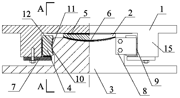
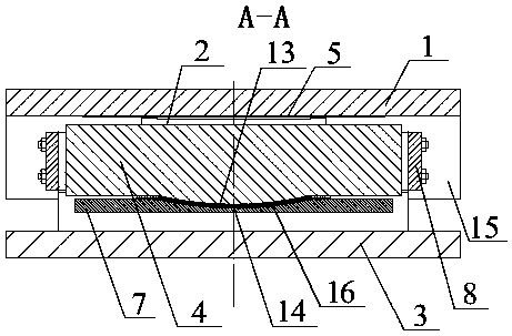
[0018] Such as figure 1 and figure 2 As shown, a multi-directional coordinated rotating one-way movable bridge bearing includes an upper seat plate 1, a middle seat plate 2 and a lower seat plate 3. The upper seat plate 1 includes an upper seat plate stopper 15 and an upper seat plate stopper 15 The boss on the top, the boss is fixed with the beam body by means of anchor bolts or welding, etc., the lower end of the upper seat plate stopper 15 is provided with a notch, the upper end of the lower seat plate 3 is located in the notch, and the lower end is passed through the anchor bolt or fixed with the bridge pier by means of welding or the like; the middle seat plate 2 is located between the upper seat plate 1 and the lower seat plate 3 and is slidably connecte...


PUM


Abstract

The invention discloses a multidirectional coordination type rotary one-way movable bridge support. The bridge support comprises an upper base plate, a middle base plate and a lower base plate; rotating blocks are arranged between the inner side of an upper base plate check block and the outer edge of the upper end of the lower base plate; the outer side surfaces of the rotating blocks are connected to the inner side wall of the upper base plate check block in a plane sliding mode; the inner side surfaces of the rotating blocks are connected to the outer edge of the upper end of the lower baseplate in a spherical sliding mode; the bottom surface of the rotating blocks are connected to horizontal rotating check blocks arranged on the two sides of the bottom of the upper base plate check block in a spherical sliding mode; and adjusting gaps for compensation of rotational displacement generated by the rotating blocks are reserved between the top surfaces of the rotating blocks and the inner wall of a notch of the upper base plate check block. According to the bridge support, all components can be in a surface contact stress state in the normal use process of the support, the stress concentration phenomenon caused by line-surface contact can be avoided, and therefore the service life can be remarkably prolonged on the premise that the safety of the support is achieved, the construction safety of a bridge can further be higher, the service life can be longer, the structure is simple, the manufacturing cost is low, installation is convenient and rapid, and good economical practicability and popularization prospect can be achieved.

Description

technical field [0001] The invention relates to a multi-directional coordinated rotating one-way movable bridge bearing, which belongs to the field of bridge bearings for bridge construction. Background technique [0002] The bridge support is an important component connecting the upper structure and the lower structure of the bridge. It reliably transmits the reaction force and deformation generated by the upper structure load to the lower structure through its own structure, and ensures that the upper and lower structures of the bridge can withstand temperature loads and concrete shrinkage. Coordinated deformation under factors such as creep and creep. At present, the bearings commonly used on road and railway bridges are divided into fixed type, one-way type and multi-directional type. The one-way movable spherical bearing should not only meet the requirements of vertical and horizontal bearing capacity, but also meet Deformation and beam corner requirements. In terms o...

Claims


Application Information

Patent Timeline
Patent Type & Authority Applications(China)
IPC IPC(8): E01D19/04
CPCE01D19/046
Inventor 潘海徐向东杜镔马白虎陈应高余军思唐志夏俊勇杨鸿波钟荣炼杨健宁响亮吴贵毅刘军冷新云
Owner GUIZHOU TRANSPORTATION PLANNING SURVEY & DESIGN ACADEME
Why Eureka
Try Eureka