Angle-adjustable imager

An imager, adjustable technology, applied in the field of imager, can solve the problems of angle adjustment range, size and shape limitation of objects

Inactive Publication Date: 2018-09-25
黄福生
View PDF7 Cites 2 Cited by
  • Summary
  • Abstract
  • Description
  • Claims
  • Application Information

AI Technical Summary

Problems solved by technology

[0005] Aiming at the deficiencies of the prior art, the present invention provides an angle-adjustable imager, which solves the problem that the angle adjustment range of the X and Y direction adjustment devices of the workbench components is easily limited by the size and shape of the object to be measured

Method used


Image

  • Angle-adjustable imager
  • Angle-adjustable imager
  • Angle-adjustable imager

Examples


Embodiment Construction

[0026] The following will clearly and completely describe the technical solutions in the embodiments of the present invention with reference to the accompanying drawings in the embodiments of the present invention. Obviously, the described embodiments are only some, not all, embodiments of the present invention. Based on the embodiments of the present invention, all other embodiments obtained by persons of ordinary skill in the art without making creative efforts belong to the protection scope of the present invention.

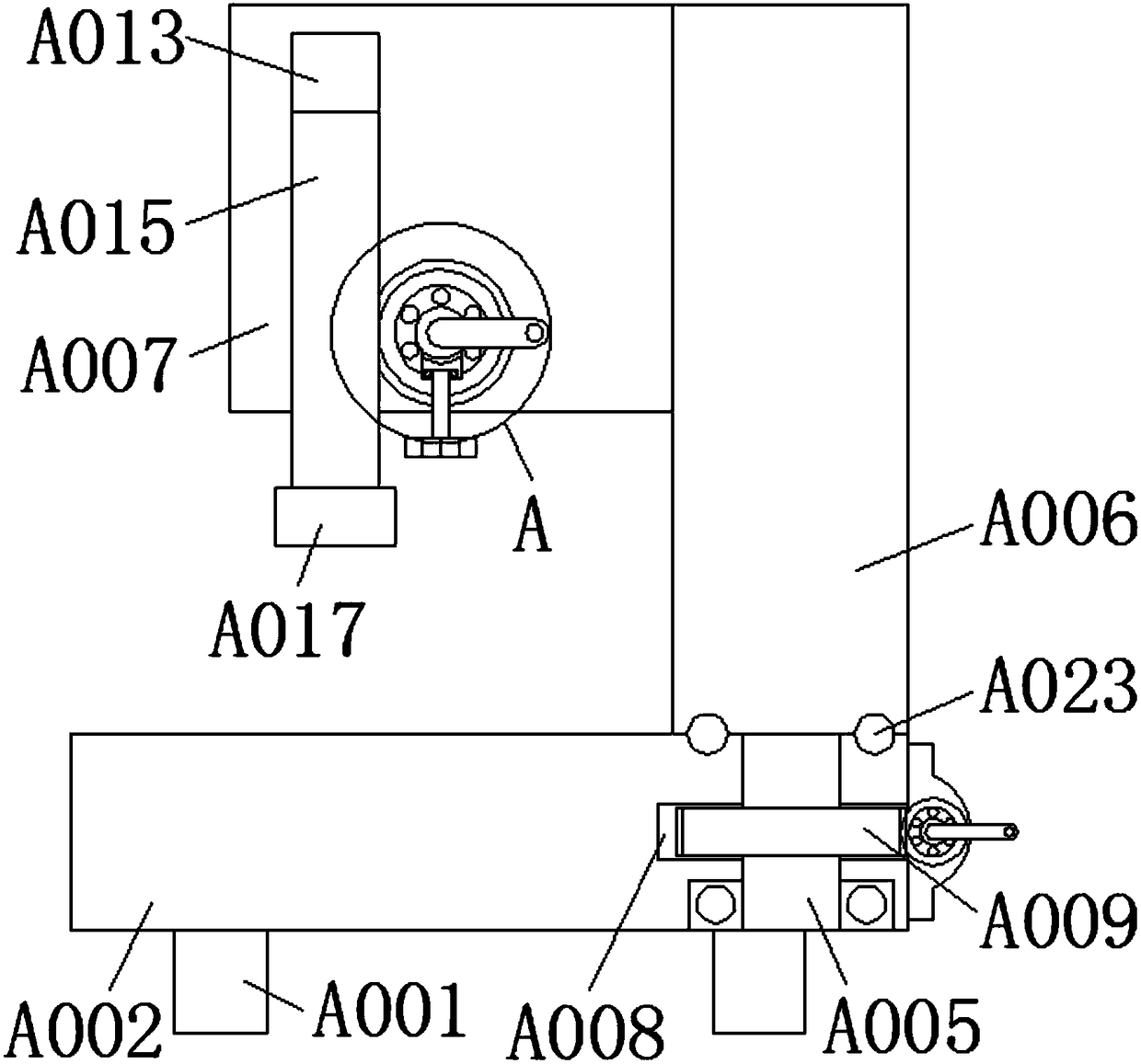
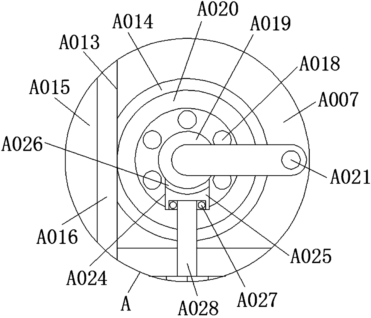
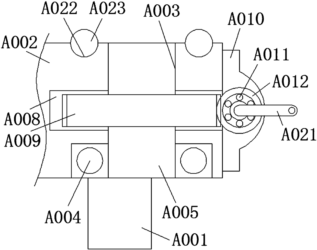
[0027] see Figure 1-3 , the present invention provides a technical solution: an angle-adjustable imager, including a support leg A001, the top of the support leg A001 is fixedly connected with an operation table A002, and the upper surface of the operation table A002 is provided with a rotation hole A003, and the rotation hole A003 is The bottom wall is fixedly connected with the first bearing A004, the inner ring of the first bearing A004 is fixedly connecte...


PUM


Abstract

The invention discloses an angle-adjustable imager, comprising supporting legs; an operating board is fixedly connected with the tops of the supporting legs; a rotating hole is formed in the upper surface of the operating board; the inner bottom wall of the rotating hole is fixedly connected with a first bearing; an inner ring of the first bearing is fixedly connected with a rotating shaft; the top of the rotating shaft is fixedly connected with a support pillar; the lower surface of the support pillar is connected with the upper surface of the operating board in a sliding way; the top of thesupport pillar is fixedly connected with a bearing block; a first placement groove is formed in the inner side wall of the rotating hole; the inner side wall of the first placement groove extends to the side face of the operating board. The angle-adjustable imager achieves the effect of adjusting the angle of the bearing block on the top of the support pillar; after a worm rotates and is meshed aworm gear, the worm gear drives the rotating shaft to rotate, so that the imager at the bottom of a lifting rod is driven to adjust the angle; therefore, the problem that the angle adjustment ranges of X and Y direction adjusting devices of a working platform part are easily limited by the size and shape of an object to be measured is effectively solved.

Description

technical field [0001] The invention relates to the technical field of imaging instruments, in particular to an angle-adjustable imaging instrument. Background technique [0002] The imager is based on computer screen measurement technology and powerful spatial geometry calculation software. Image measuring instrument is divided into automatic image measuring instrument (also known as CNC image measuring instrument) and manual image measuring instrument. The imager uses non-contact measurement as the main measurement method. Through the accumulation of long-term technical experience, the function of the automatic imager has been gradually extended. With the use of probes and laser groups, there has been a measurement between two-dimensional and three-dimensional geometric dimensions. The instrument is called "2.5D image measuring instrument" in the industry. [0003] At present, when the imager needs to be adjusted in use, most of them rely on the X and Y adjustment device...

Claims


Application Information

Patent Timeline
Patent Type & Authority Applications(China)
IPC IPC(8): F16M11/18F16M11/12
CPCF16M11/12F16M11/18
Inventor 黄福生
Owner 黄福生
Why Eureka
Try Eureka