
Rotor of rotary electric machine

A technology for rotating electrical machines and rotors, applied in the field of rotors of rotating electrical machines, can solve the problems of increased motor manufacturing costs and complicated manufacturing processes, and achieve the effects of improving torque performance, maximizing demagnetization resistance, and increasing demagnetization resistance.

Active Publication Date: 2018-09-25
HONDA MOTOR CO LTD
View PDF7 Cites 0 Cited by
  • Summary
  • Abstract
  • Description
  • Claims
  • Application Information

AI Technical Summary

Problems solved by technology

Ribs on the rotor core also complicate the manufacturing process of the rotor, increasing the manufacturing cost of the motor

Method used


Image

  • Rotor of rotary electric machine
  • Rotor of rotary electric machine
  • Rotor of rotary electric machine

Examples


Embodiment Construction

[0056] Embodiments of the present invention will be described below based on the drawings. It should be noted that the drawings are views viewed along the direction of symbols.

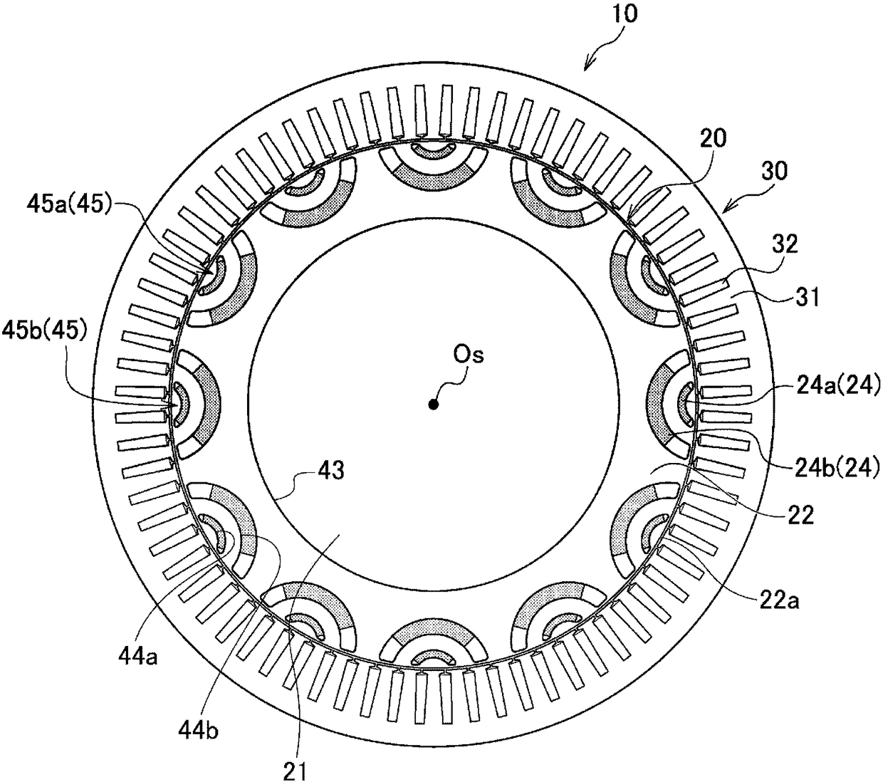
[0057] figure 1 It is a radial cross-sectional view of the rotating electrical machine according to one embodiment. figure 1 The illustrated rotating electrical machine 10 includes a rotor 20 and a stator 30 disposed opposite to each other with a slight gap on the radially outer side of the rotor 20 . The rotating electrical machine 10 is configured to rotate the rotor 20 by energizing the coil 32 wound around the teeth 31 of the stator 30 .

[0058] The rotor 20 is a rotor of a so-called embedded permanent magnet rotating electrical machine (IPM motor), and has a rotating shaft 21 rotatably supported by a not-shown frame, a rotor core 22 fixed to the outer peripheral surface of the rotating shaft 21, And a plurality of permanent magnets 24 embedded in the rotor core 22 .

[0059] The rotor core 2...


PUM


Abstract

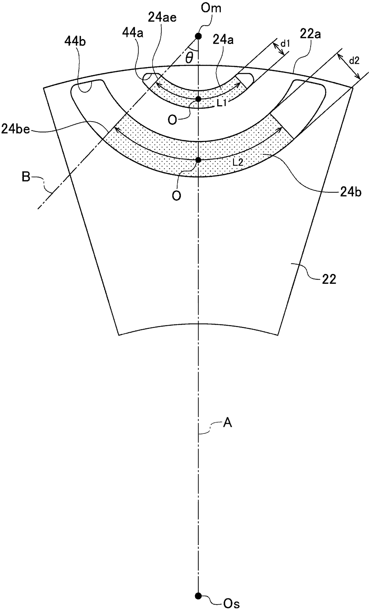
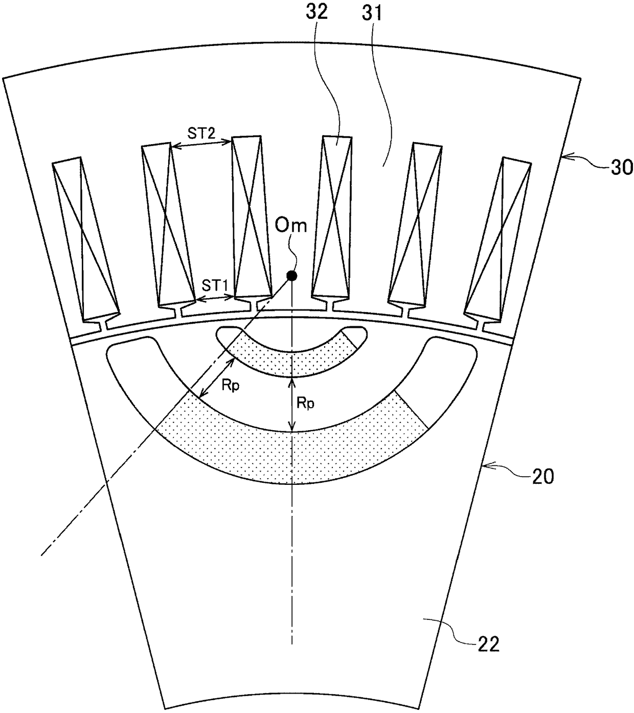
A rotor of a rotary electric machine, improving demagnetization resistance, is provided. The rotor includes a rotor core of an approximately annular shape which has plural sets of plural magnet insertion holes arranged radially, the plural sets being arranged in a circumferential direction with a predetermined gap, and permanent magnets which are inserted into the magnet insertion holes, respectively. Each permanent magnet has a circular arc shape in a radial section, and a curved surface thereof is convex toward a rotation shaft of the rotor. The plural permanent magnets which are respectively inserted into the radially arranged plural magnet insertion holes in each set include a first permanent magnet which is positioned on an outer circumferential surface side and a second permanent magnet which is positioned on a rotation shaft side and has a radial thickness equal to or larger than a radial thickness of the first permanent magnet.

Description

technical field [0001] The invention relates to a rotor for a rotating electrical machine. Background technique [0002] In the rotor of the motor described in Patent Document 1, the permanent magnets embedded in an arc shape projecting inside the rotor, that is, the outermost permanent magnets, and the outermost permanent magnets embedded in the rotor in parallel with the outermost permanent magnets are provided inside. The permanent magnet is the inner permanent magnet. In the embedded permanent magnet synchronous motor (IPM synchronous motor) described in Patent Document 1, a reverse magnetic field is applied to the permanent magnet by a rotating magnetic field, and the reverse magnetic field acts as a demagnetizing field for the permanent magnet. Where a strong demagnetization field acts, the coercive force of the permanent magnet is small, and demagnetization may occur. If it is used in a state where demagnetization is likely to occur, there is a high possibility that...

Claims


Application Information

Patent Timeline
Patent Type & Authority Applications(China)
IPC IPC(8): H02K1/27H02K1/24
CPCH02K1/246H02K1/2766H02K2213/03H02K21/14
Inventor 相马慎吾久保田芳永
Owner HONDA MOTOR CO LTD
Learn More