Stepping motor

A stepping motor and stator iron core technology, applied in electrical components, electromechanical devices, magnetic circuit shape/style/structure, etc. Saturation and other problems, to achieve the effect of improving the magnetic density distribution, ensuring the slot area, and reducing the magnetic density

Pending Publication Date: 2018-09-25
SHANGHAI MOONS ELECTRICAL APPLIANCE
View PDF0 Cites 0 Cited by
  • Summary
  • Abstract
  • Description
  • Claims
  • Application Information

AI Technical Summary

Problems solved by technology

[0008] If the size of the main pole of the stator is small, it will cause excessive saturation of the magnetic density of the main pole of the motor, which will affect the output torque of the motor, especially the saturation degree of the stepping motor is serious at high speed, and the high-speed torque is small

Method used


Image

  • Stepping motor
  • Stepping motor
  • Stepping motor

Examples


Embodiment 1

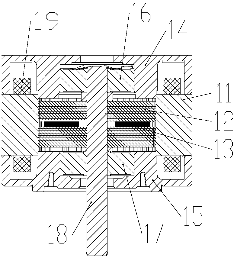
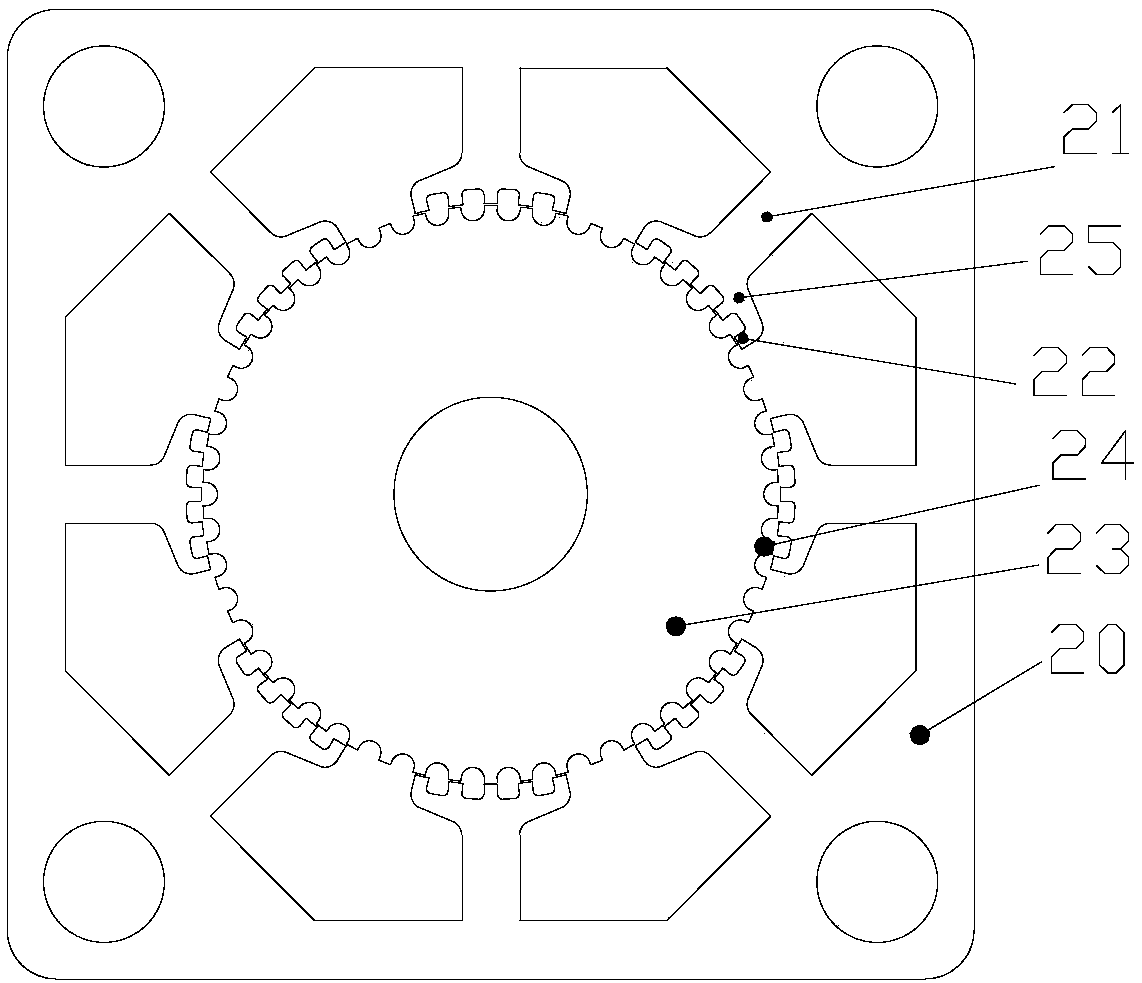
[0044] A stepper motor, including a stator core 11 and a rotor core 12, the stator core 11 includes a stator core body 20, and the stator core body 20 is evenly distributed with 8 stator main poles along the circumferential direction 21. The pole shoe 25 of each stator main pole 21 is provided with a plurality of evenly distributed stator small teeth 22, and the width of the stator main pole 21 gradually increases from outside to inside.

[0045] Such as Image 6 As shown, because the magnetic density in area A is relatively saturated, increase the width of the main pole in area A to Bp2; the magnetic density saturation in area C is low, reduce the width of the main pole in area C to Bp1, and the entire main pole changes from a rectangle to a trapezoid.

[0046] The stator main pole 21 has a trapezoidal structure, its small end is connected to the stator core yoke ( 26 ), and its large end is connected to the pole shoe 25 .

[0047] The specific size of the trapezoidal struct...

Embodiment 2

[0051] Such as Figure 7 As shown, because the magnetic density in area A is relatively saturated, increase the width of the main pole in area A to Bp2; the magnetic density saturation in area C is low, reduce the width of the main pole in area C to Bp1, and the entire main pole changes from a single rectangle to an edge The radial direction is composed of two rectangular main pole parts from large to small.

[0052] The main pole of the stator has a first-order boss structure.

[0053] The specific size of the first-order boss structure is as follows:

[0054] Bt*N*0.5≤Bp1

[0055] Among them, Bp1 is the width of the convex part of the small head, L1 is the length of the convex part of the small head, Bp2 is the width of the bottom of the big head, L2 is the length of the bottom of the big head, Bt is the width of the small teeth of the stator, and N is the stator on the main pole of a single stator Number of small teeth.

Embodiment 3

[0057] Such as Figure 8 As shown, the entire main pole changes from a single rectangle to a combination of three rectangular main pole parts from large to small along the radial direction. The main pole of the stator has a second-order boss structure.

[0058] The specific size of the second-order boss structure is as follows:

[0059] Bt*N*0.5≤Bp1

[0060] Among them, Bp1 is the width of the convex part of the small head, L1 is the length of the convex part of the small head, Bp2 is the width of the middle step, L2 is the length of the middle step, Bp3 is the width of the bottom of the big head, L3 is the length of the bottom of the big head, and Bt is the stator The width of the small teeth, N is the number of stator small teeth on a single stator main pole.


PUM


Abstract

The invention relates to a stepping motor. The stepping motor includes a stator core (11) and a rotor core (12). The stator core (11) includes a stator core body (20); the stator core body (20) is uniformly provided with eight stator main poles (21) along with a peripheral direction; a pole shoe part (25) of each of the stator main poles (21) is provided with multiple uniformly distributed statortoothlets; and the width of each of the stator main poles (21) is gradually increased from outside to inside. Compared with the prior art, the stepping motor has the advantages of improving the main pole magnetic density distribution of the motor, reducing the saturation degree of the motor, increasing the output torque of the motor, and the like by increasing the width of the main poles near thepole shoe part.

Description

technical field [0001] The invention relates to a motor, in particular to a stepping motor. Background technique [0002] Such as figure 1 with figure 2 As shown, the existing hybrid stepping motor includes a stator core 11, a rotor core 12, a magnetic steel 13, a rear end cover 14, a front end cover 15, a rear bearing 16, a front bearing 17, a rotating shaft 18 and a winding 19; [0003] Hybrid stepper motor cross section such as image 3 As shown, the stator core body 20 is evenly distributed with eight stator main poles 21 along the circumferential direction, and there are several evenly distributed stator small teeth 22 on the pole shoe part 25 of each main pole, the rotor core body 23 and the stator iron The core body 20 is concentric with the center of the circle, and several rotor teeth 24 are evenly distributed in the circumferential direction; [0004] Figure 4 It is a schematic diagram of the stator main pole, the width of the stator main pole 21 is Bp, and ...

Claims


Application Information

Patent Timeline
Patent Type & Authority Applications(China)
IPC IPC(8): H02K37/04H02K1/14
CPCH02K1/14H02K37/04H02K2213/03
Inventor 彭光明金万兵张喜臣林聪明
Owner SHANGHAI MOONS ELECTRICAL APPLIANCE
Why Eureka
Try Eureka