Camera assembly of electronic equipment and electronic equipment

A technology of camera components and electronic equipment, applied to color TV parts, TV system parts, electrical components, etc., can solve the problems of difficult installation, long time spent, complicated installation process, etc., and achieve simple assembly , improve assembly efficiency, and achieve the effect of fixed connection

Pending Publication Date: 2018-09-25
OPPO CHONGQING INTELLIGENT TECH CO LTD
View PDF0 Cites 1 Cited by
  • Summary
  • Abstract
  • Description
  • Claims
  • Application Information

AI Technical Summary

Problems solved by technology

[0002] In the related art, when the camera assembly is assembled with the electronic equipment, it is difficult to install the camera assembly and the electronic equipment in alignment, and the installation process is relatively complicated. It takes a long time for technicians to assemble and fix the camera assembly, and the assembly efficiency is low. lower

Method used


Image

  • Camera assembly of electronic equipment and electronic equipment
  • Camera assembly of electronic equipment and electronic equipment
  • Camera assembly of electronic equipment and electronic equipment

Examples


Embodiment 1

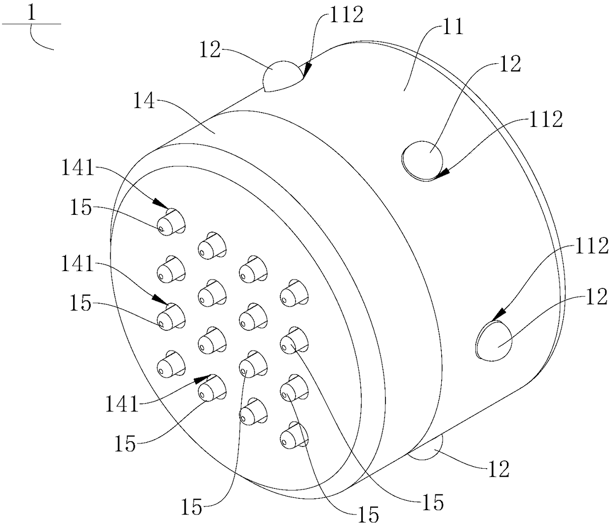
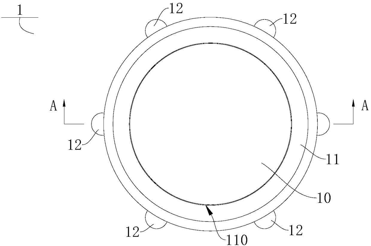
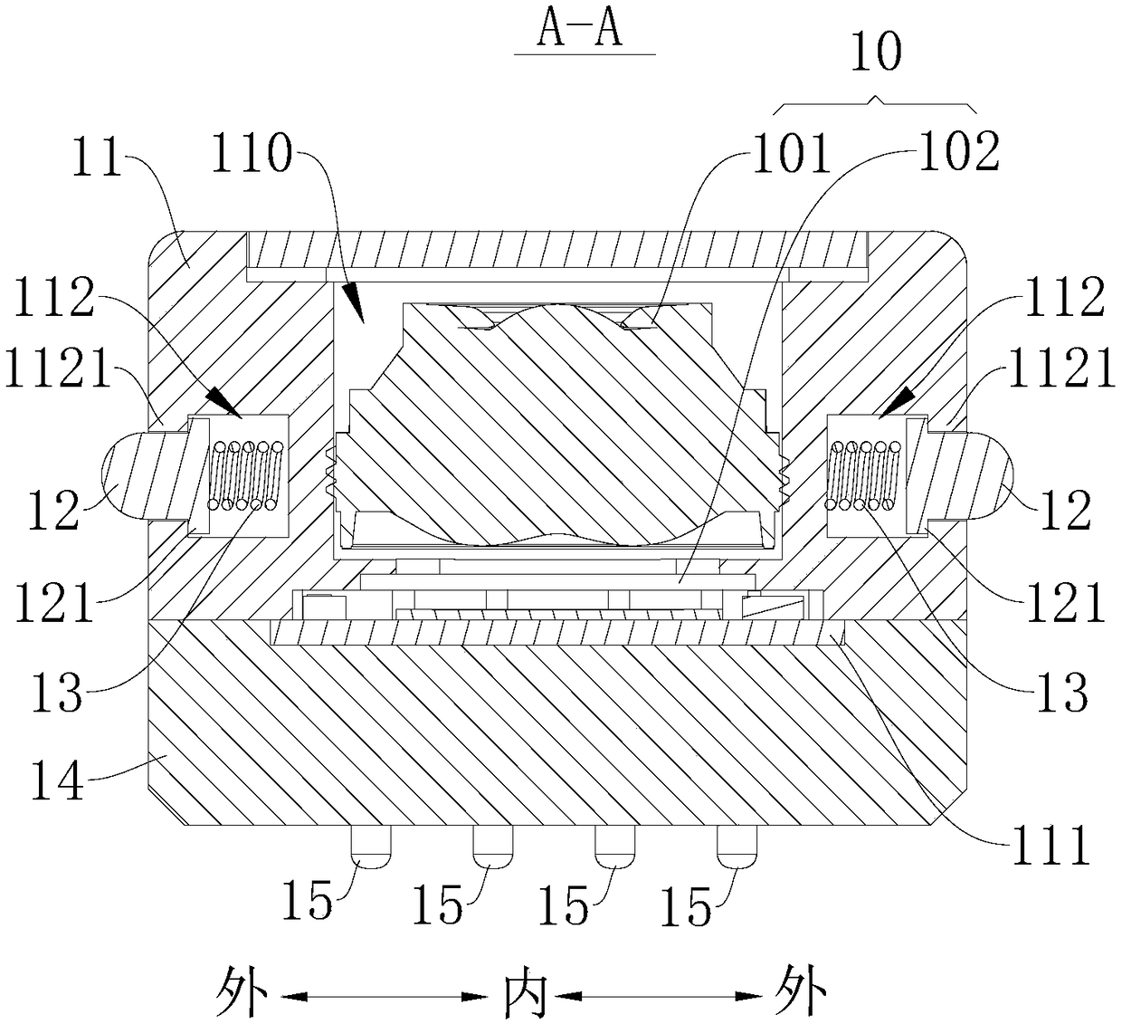
[0065] Such as figure 1 , image 3 and Figure 4 As shown, the camera assembly 1 includes: a lens assembly 10, a bracket 11, a limit block 12, an elastic member 13 and a fixing frame 14, the bracket 11 is configured as a cylinder, the bracket 11 has an installation cavity 110, and the lens assembly 10 is located in the installation cavity within 110. The lens assembly 10 includes: a lens 101 and a photosensitive chip 102 .

[0066] Such as image 3 and Figure 4 As shown, the outer peripheral wall of the bracket 11 is provided with a plurality of installation holes 112 evenly spaced along the circumferential direction of the bracket 11 , and the plurality of installation holes 112 are located in the same height plane of the bracket 11 . A limiting block 12 is arranged in the mounting hole 112 , and the end surface of the limiting block 12 away from the bottom wall of the mounting hole 112 is a hemispherical surface, and the limiting block 12 can cooperate with the limitin...

Embodiment 2

[0070] The structure of this embodiment is substantially the same as that of Embodiment 1, wherein the same components use the same reference numerals, the difference is that a plurality of spring pins 15 are arranged at intervals on the circuit board 22, and the bracket 11 is provided with The circuit board 22 and the camera assembly 1 are electrically connected through the cooperation of the spring pin 15 and the contact 16 .


PUM


Abstract

The invention discloses a camera assembly of electronic equipment and the electronic equipment. The camera assembly comprises a lens assembly, and a bracket, wherein the lens assembly is arranged on the bracket; multiple spaced mounting holes are formed in the peripheral wall of the bracket along the circumferential direction of the bracket; the camera assembly further comprises multiple limitingblocks, which are arranged in the mounting holes, and multiple elastic pieces which are arranged between the bottom walls of the mounting holes and the limiting blocks, so as to push the limiting blocks to move towards the outer sides of the mounting holes; a mounting frame is arranged inside the electronic equipment; the mounting frame is provided with a mounting slot for mounting the camera assembly; and multiple limiting slots matched with the limiting blocks are formed in the inner wall of the mounting slot. According to the camera assembly of the electronic equipment, redundant assemblingpieces and a connection working procedure are eliminated, so that the assembling is simpler; and the assembling efficiency of the camera assembly can be improved.

Description

technical field [0001] The present application relates to the technical field of communication equipment, and in particular to a camera assembly of an electronic equipment and the electronic equipment. Background technique [0002] In the related art, when the camera assembly is assembled with the electronic equipment, it is difficult to install the camera assembly and the electronic equipment in alignment, and the installation process is relatively complicated. It takes a long time for technicians to assemble and fix the camera assembly, and the assembly efficiency is low. lower. Contents of the invention [0003] The present application aims to solve at least one of the above-mentioned technical problems. Therefore, an object of the present application is to provide a camera assembly of an electronic device, which has the advantage of being easy to assemble. [0004] Another object of the present application is to provide an electronic device, which includes the above-...

Claims


Application Information

Patent Timeline
Patent Type & Authority Applications(China)
IPC IPC(8): H04N5/225H04M1/02
CPCH04M1/0264H04N23/57H04N23/55
Inventor 张文真
Owner OPPO CHONGQING INTELLIGENT TECH CO LTD
Why Eureka
Try Eureka