Automatic pipe cutting machine and operation method

A pipe cutting machine and automatic technology, applied in metal sawing equipment, sawing machine equipment, metal processing equipment and other directions, can solve the problems of low production efficiency, high production cost, poor product quality, etc., to improve production efficiency, simple structure, The effect of reducing labor intensity

Active Publication Date: 2018-09-28
CHINA THREE GORGES UNIV
View PDF8 Cites 9 Cited by
  • Summary
  • Abstract
  • Description
  • Claims
  • Application Information

AI Technical Summary

Problems solved by technology

[0003] In traditional industrial production, the relatively backward method of hand-cut metal pipes has been used for a long time for mass production, which not only has high labor intensity and low production efficiency, but also has poor product quality and low pass rate, which in turn leads to high production costs.

Method used


Image

  • Automatic pipe cutting machine and operation method
  • Automatic pipe cutting machine and operation method

Examples


Embodiment 1

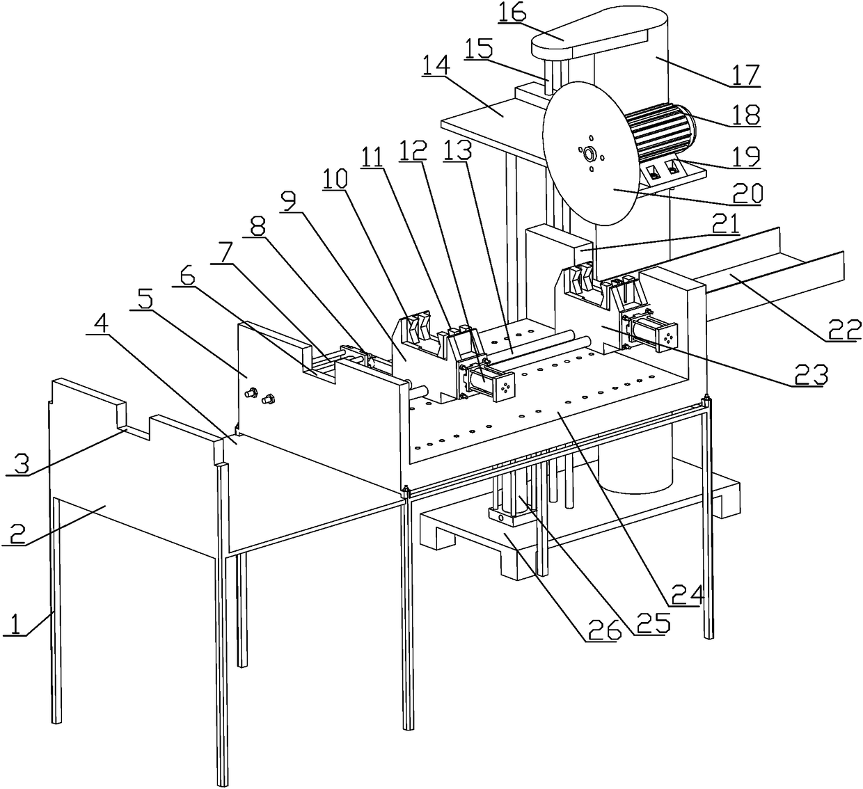
[0032] see Figure 1-2 , an automatic pipe cutting machine, which includes a frame 1, a first platform 4 and a second platform 24 are fixed on the top of the frame 1, and a support assembly for supporting pipe fittings is arranged on the first platform 4, The second platform 24 is provided with a delivery device for pushing and feeding the pipe fittings, and a fixed clamping device 23 for clamping and fixing the pipe fittings is installed at the end of the delivery device. Cutting device for pipe cutting. By adopting the automatic pipe cutting machine with the above structure, it can be used for automatic cutting of metal pipe fittings. During use, it is only necessary to place the metal pipe fittings on the top of the frame 1, and transport them through the conveying device to reach the set value. The cutting length is fixed by the fixed clamping device 23, and finally, it is automatically cut by the cutting device, thereby improving work efficiency, increasing the degree of...

Embodiment 2

[0043] The operating method of any one of the automatic pipe cutting machines, comprising the following steps:

[0044] Step1: Place the pipe to be cut on the top limit grooves of the first support plate 2 and the second support plate 5, and place the end of the pipe between the fixed clamp 10 and the movable clamp 11 of the feeding clamping device between;

[0045] Step2: Start the clamping cylinder 12 of the feeding and clamping device to clamp the pipe fittings;

[0046] Step3: Start the pushing cylinder 7, drive the feeding clamping device to slide along the horizontal slide rail 13 through the pushing cylinder 7, and then transport the pipe fittings so that the other end passes through the fixed clamping device 23;

[0047] Step4: Multiple times of reciprocating control feeding and clamping device to transport the pipe fittings until the set cutting length is reached;

[0048] Step5: Start the fixed clamping device 23 to clamp and fix the pipe fittings;

[0049] Step6:...


PUM


Abstract

The invention discloses an automatic pipe cutting machine and an operation method. The automatic pipe cutting machine comprises a rack. A first platform and a second platform are fixed to the top of the rack. The first platform is provided with a supporting assembly for supporting a pipe fitting. The second platform is provided with a conveying device for pushing and feeding the pipe fitting. Thetail end of the conveying device is provided with a fixing and clamping device for clamping and fixing the pipe fitting. The side face of the second platform is provided with a cutting device for cutting the pipe fitting. The supporting assembly comprises a first supporting plate and a second supporting plate. A first limiting groove is machined in the center position of the top of the first supporting plate, and a second limiting groove is machined in the center position of the top of the second supporting plate.

Description

technical field [0001] The invention relates to the field of cutting equipment, in particular to an automatic pipe cutting machine and an operation method. Background technique [0002] Pipe cutting machine plays a pivotal role in many manufacturing industries. It can transform traditional manual work into mass production, greatly improve production efficiency, significantly reduce labor intensity of workers, and more importantly, improve product quality. significantly improved. Therefore, pipe cutting machines are widely used in many manufacturing industries. [0003] In traditional industrial production, the relatively backward method of hand-cut metal pipes has been used for a long time for mass production, which not only has high labor intensity and low production efficiency, but also has poor product quality and low pass rate, which in turn leads to high production costs. With the rapid development and higher requirements of the machinery manufacturing industry, the d...

Claims


Application Information

Patent Timeline
Patent Type & Authority Applications(China)
IPC IPC(8): B23D47/00B23D47/02B23D47/04B23D47/10
CPCB23D47/00B23D47/02B23D47/04B23D47/042B23D47/10
Inventor 钟先友兰旺李宝万陈诗昊
Owner CHINA THREE GORGES UNIV
Why Eureka
Try Eureka