
Machine tool with floating shaft

A technology of floating shafts and machine tools, which is applied to machine tools suitable for grinding the edge of workpieces, parts of grinding machine tools, grinding machines, etc. It can solve problems such as the absence of floating shafts, achieve simple structure, improve surface quality, and facilitate disassembly and assembly Effect

Pending Publication Date: 2018-09-28
CHONGQING ROBEST INTELLIGENT EQUIP CO LTD
View PDF5 Cites 2 Cited by
  • Summary
  • Abstract
  • Description
  • Claims
  • Application Information

AI Technical Summary

Problems solved by technology

[0003] At present, there are many structural forms of floating deburring spindles, such as a radial floating deburring spindle structure with application number 201720024249.5, a radial flexible deburring spindle with application number 201621071100.4, and a diameter with application number To the flexible deburring spindle, a floating deburring adaptive device with an application number of 201510452612.9, a robot floating deburring device with an application number of 201621322134.6, etc., mentioned various structural principles about the floating shaft, but similar The application of floating axes on machine tools has not yet appeared

Method used


Image

  • Machine tool with floating shaft

Examples


Embodiment

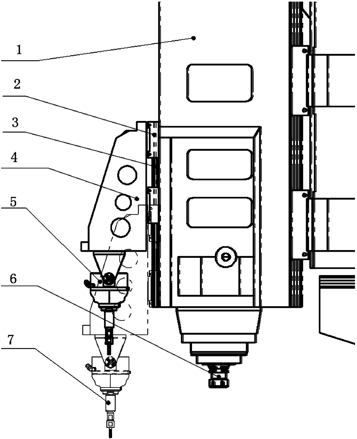
[0024] like figure 1 As shown, a machine tool with a floating axis includes a Z-axis body 1 of the machine tool. A rigid output shaft 6 is provided at the lower end of the Z-axis body 1 of the machine tool. The Z-axis body 1 of the machine tool is installed on the Z-axis guide rail of the machine tool. The Z-axis body 1 is provided with a floating shaft 5 and a power device (not shown in the figure), and the power device is used to push the floating shaft 5 to move up and down to realize output switching between the rigid output shaft 6 and the floating shaft 5 .

[0025] At present, the existing machine tools on the market all include machine tool Z-axis body 1, the lower end of Z-axis body 1 is provided with a rigid output shaft 6, the lower end of rigid output shaft 6 is equipped with a tool, and the machine tool Z-axis body 1 is installed on the Z-axis guide rail of the machine tool , when working, the Z-axis body 1 of the machine tool moves up and down along the Z-axis gu...


PUM


Abstract

The invention discloses a machine tool with a floating shaft. The machine tool with the floating shaft comprises a machine tool Z-axis body, wherein the machine tool Z-axis body is arranged on a machine tool Z-axis guide rail; a rigid output shaft is arranged at the lower end of the machine tool Z-axis body; the floating shaft and a power device are arranged on the machine tool Z-axis body; and the floating shaft is arranged on the machine tool Z-axis body through an installing mechanism and can move under the action of the power device, so that the switching of the output shaft and the floating shaft is realized during processing. The machine tool with the floating shaft combines the technologies of a traditional floating shaft; the rigid output shaft and the floating shaft can be freelyswitched; when the common processing is carried out (for example, the surfaces of part of regular castings are polished), the quality of products can be ensured very well by adopting the rigid output;when the special processing is carried out (for example, the surfaces of part of irregular castings are burred, ground or polished), the undercutting problem of workpieces can be effectively avoidedby adopting the floating shaft output; and the surface quality and product yield of workpieces are improved.

Description

technical field [0001] The invention belongs to the technical field of machining equipment, in particular to a machine tool with a floating shaft. Background technique [0002] At present, most factories and even large engine manufacturing companies use manual or hand-held pneumatic and electric tools for deburring and grinding of engine casings, car bodies and other workpieces, which can easily lead to product defect rates. rise, and the efficiency is very low, and there are problems such as rough and uneven surface of the processed product. For this reason, some manufacturers have begun to use robots to install electric or pneumatic tools for automatic grinding. Compared with hand-held grinding, robot deburring can effectively improve production efficiency, reduce costs, and improve product yield. However, due to other factors such as mechanical arm rigidity and positioning errors , use robots to clamp electric and pneumatic tools to deburr. When dealing with irregular bu...

Claims


Application Information

Patent Timeline
Patent Type & Authority Applications(China)
IPC IPC(8): B24B9/00B24B41/04
CPCB24B9/00B24B41/04
Inventor 尚智强
Owner CHONGQING ROBEST INTELLIGENT EQUIP CO LTD
Learn More