Discharging door of vertical shaft stirrer
A discharge door and mixer technology, which is applied in the field of concrete mixing, can solve the problems of fast wear of the tank sealant, and the gap between the discharge door and the tank sealant cannot be adjusted adaptively, so that it is not easy to leak slurry, open or close the door Simple and easy, reduce wear effect
- Summary
- Abstract
- Description
- Claims
- Application Information
AI Technical Summary
Problems solved by technology
Method used
Image
Examples
Embodiment 1
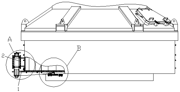
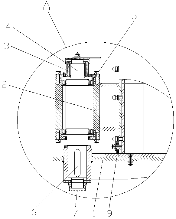
[0037]The discharge door of the vertical shaft mixer includes the discharge door body 1 and the discharge door seat 2 fixed on the tank body, and also includes the fixed seat 3, the discharge door shaft 4, the bearing 5, the flat key 6 and the compression nut 7. The discharge door shaft 4 is installed in the discharge door seat 2 through the bearing 5, the top of the discharge door shaft 4 is a threaded screw rod, and the top of the discharge door shaft 4 is connected with the fixed seat 3 by threads, and the fixed seat 3 Fixed on the discharge door seat 2, the discharge door body 1 is connected with the discharge door shaft 4 through the flat key 6 and fixed on the discharge door shaft 4 through the compression nut 7, the discharge door body 1 A discharge door sealant 8 for sealing contact with the discharge door of the tank body is provided, and a tank body sealant 9 for sealing contact with the upper surface of the discharge door body 1 is provided on the tank body.
[0038...
Embodiment 2
[0040] The discharge door of the vertical shaft mixer includes the discharge door body 1 and the discharge door seat 2 fixed on the tank body, and also includes the fixed seat 3, the discharge door shaft 4, the bearing 5, the flat key 6 and the compression nut 7. The discharge door shaft 4 is installed in the discharge door seat 2 through the bearing 5, the top of the discharge door shaft 4 is a threaded screw rod, and the top of the discharge door shaft 4 is connected with the fixed seat 3 by threads, and the fixed seat 3 Fixed on the discharge door seat 2, the discharge door body 1 is connected with the discharge door shaft 4 through the flat key 6 and fixed on the discharge door shaft 4 through the compression nut 7, the discharge door body 1 A discharge door sealant 8 for sealing contact with the discharge door of the tank body is provided, and a tank body sealant 9 for sealing contact with the upper surface of the discharge door body 1 is provided on the tank body.
[004...
Embodiment 3
[0046] The discharge door of the vertical shaft mixer includes the discharge door body 1 and the discharge door seat 2 fixed on the tank body, and also includes the fixed seat 3, the discharge door shaft 4, the bearing 5, the flat key 6 and the compression nut 7. The discharge door shaft 4 is installed in the discharge door seat 2 through the bearing 5, the top of the discharge door shaft 4 is a threaded screw rod, and the top of the discharge door shaft 4 is connected with the fixed seat 3 by threads, and the fixed seat 3 Fixed on the discharge door seat 2, the discharge door body 1 is connected with the discharge door shaft 4 through the flat key 6 and fixed on the discharge door shaft 4 through the compression nut 7, the discharge door body 1 A discharge door sealant 8 for sealing contact with the discharge door of the tank body is provided, and a tank body sealant 9 for sealing contact with the upper surface of the discharge door body 1 is provided on the tank body.
[004...
PUM
 Abstract
Description
Claims
Application Information
 - R&D
- Intellectual Property
- Life Sciences
- Materials
- Tech Scout
- Unparalleled Data Quality
- Higher Quality Content
- 60% Fewer Hallucinations
Browse by: Latest US Patents, China's latest patents, Technical Efficacy Thesaurus, Application Domain, Technology Topic, Popular Technical Reports.
© 2025 PatSnap. All rights reserved.Legal|Privacy policy|Modern Slavery Act Transparency Statement|Sitemap|About US| Contact US: help@patsnap.com


