Foam plate extrusion production line

A foamed board and production line technology, applied in metal processing and other directions, can solve the problems of non-continuous foamed board production in the production line and reduce the production efficiency of the production line, and achieve the effects of improving cutting efficiency, improving cutting effect and improving production efficiency.

Active Publication Date: 2018-09-28
南京昊翔机械制造有限公司
View PDF3 Cites 4 Cited by
  • Summary
  • Abstract
  • Description
  • Claims
  • Application Information

AI Technical Summary

Problems solved by technology

[0003] The existing foam board production line includes a crushing device, a powder milling device, a powder mixing device, a twin-screw extruder, a shaping table, a tractor, and a cutting machine connected in sequence. The cutting machine includes a frame on which there are Conveyor belt, facing the position where the foam board on the conveyor belt is provided with a first cutter for cutting the continuous foam board into segmented foam boards, the frame is also provided with a first cutter for driving the first cutter The cylinder moving towards the foamed board, when the foamed board is conveyed under the first cutter, it is necessary to stop the conveyor belt to wait for the cylinder to drive and move towards the foamed board, so that the first cutter completes the segmentation of the continuously produced foamed board Cutting, this process that needs to stop the conveyor belt and wait for the first cutter to cut, reduces the production efficiency of the entire production line, making the production line unable to continuously complete the production of foam boards

Method used


Image

  • Foam plate extrusion production line
  • Foam plate extrusion production line
  • Foam plate extrusion production line

Examples


Embodiment

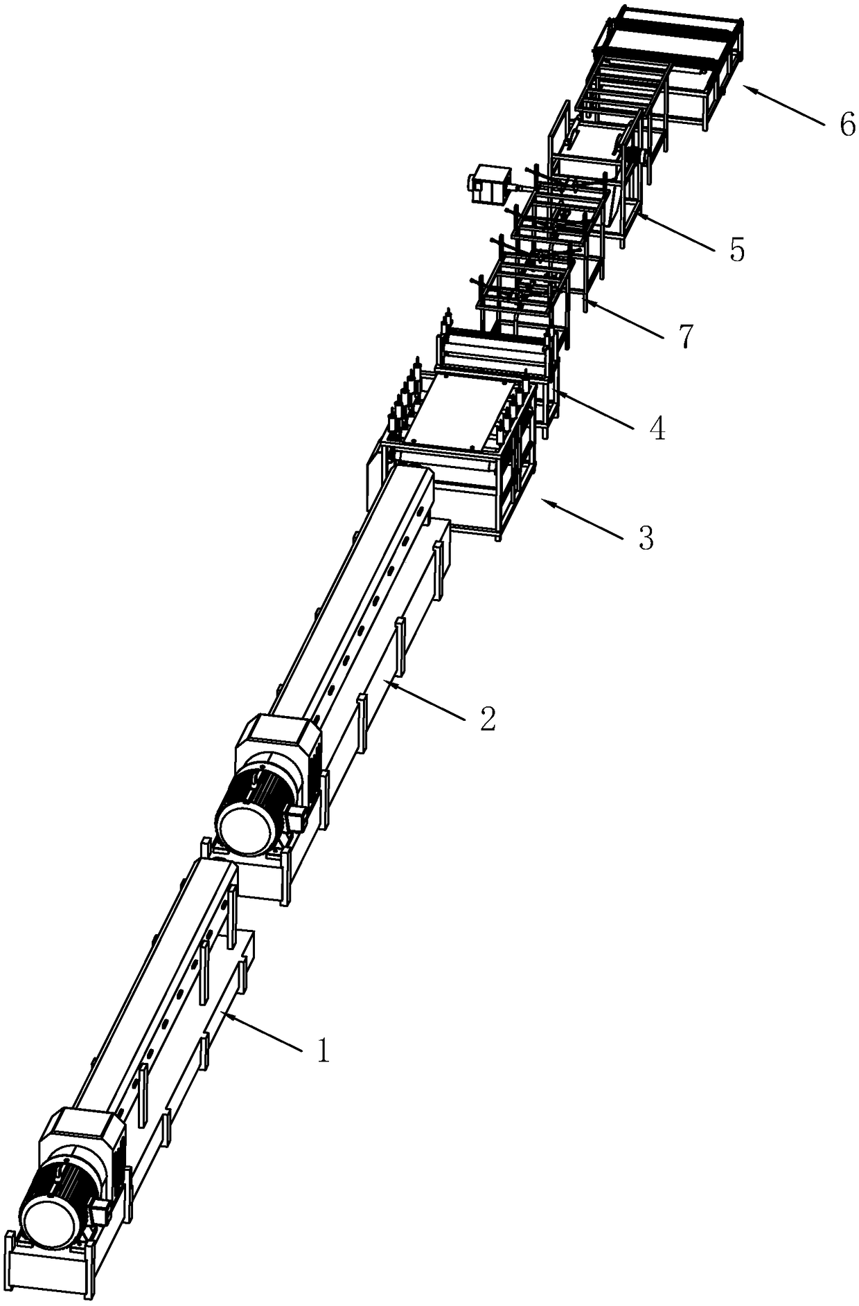
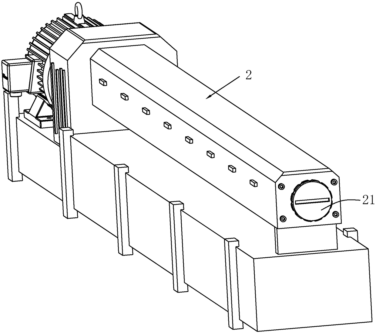
[0043] combine figure 1 with figure 2 , a foam board extrusion production line, including a twin-screw extruder 1, a single-screw extruder 2, a whole platform 3, an embossing table 4, an edge trimming saw 5 and a double cutting saw 6, and an embossing table 4 and A material shelf 7 is arranged between the side trimming saws 5, and a mold 21 for molding extruded polyvinyl chloride is arranged on the output end of the single-screw extruder 2.

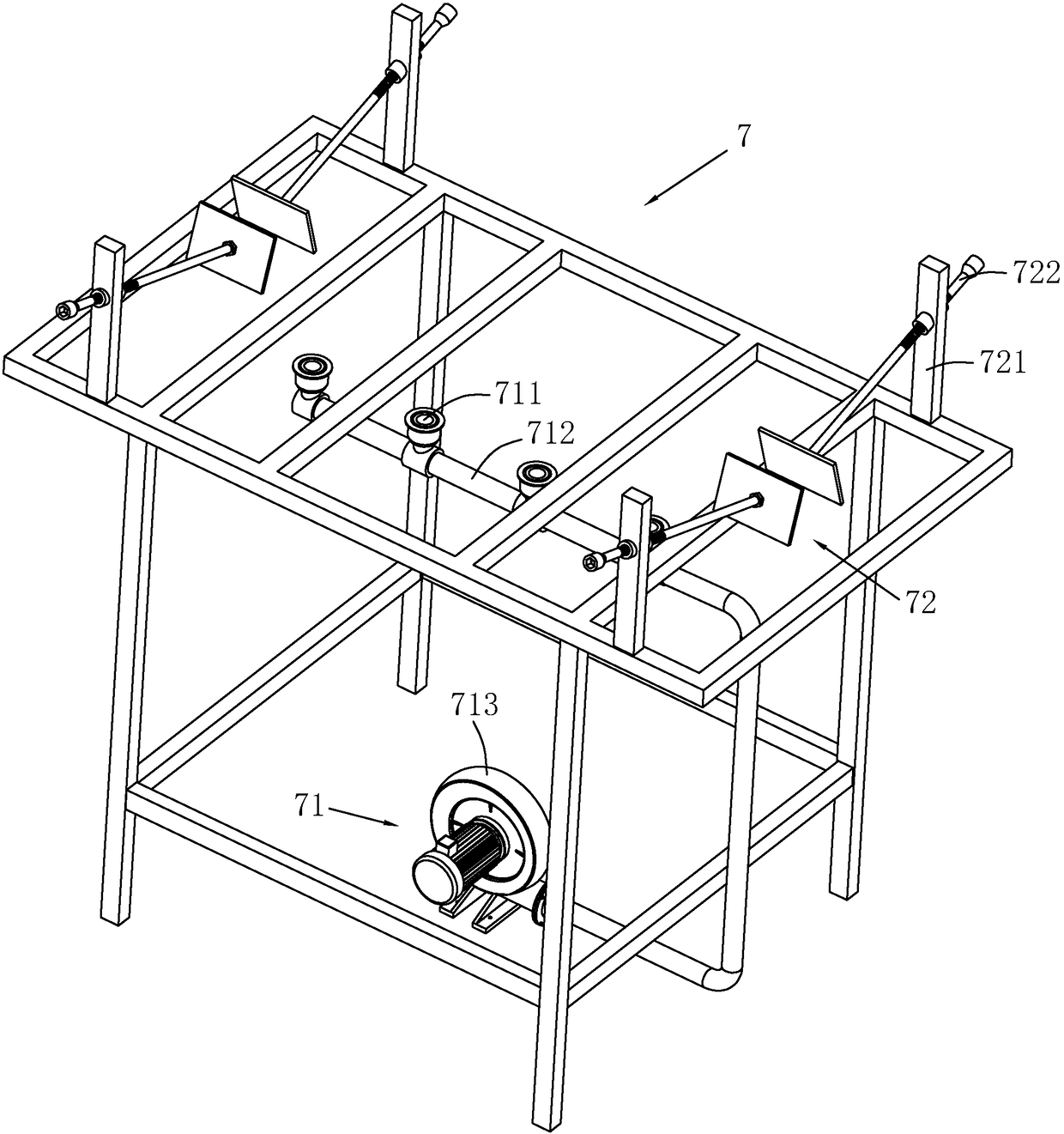
[0044] combine figure 1 with figure 2 , the material rack 7 is provided with a cooling device 71 for cooling the foam board, and the cooling device 71 includes a plurality of ventilation pipes 711 arranged below the material rack 7 towards the foam board on the material rack 7, and a plurality of ventilation pipes 711 pass through the pipeline 712 In communication, the end of the pipe 712 is provided with a blower 713 for blowing air into the ventilation pipe 711 . The foamed board output by the single-screw extruder 2 has a relativ...


PUM

PropertyMeasurementUnit
compressive strengthaaaaaaaaaa

Abstract

The invention relates to a foam plate extrusion production line. The foam plate extrusion production line comprises a double-cutting saw, and the double-cutting saw comprises a machine frame. A conveyor belt and a cutting device are arranged on the machine frame. The cutting device comprises connecting rods arranged on the both sides, in the transmission direction, of the machine frame. Rotating shafts are rotatably arranged in the connecting rods on both sides in a crossing mode. Fixed rods are arranged on the position, in the circumferential direction, of the rotating shafts. Telescopic rodsare arranged on the end portions, away from the rotating shafts, of the fixed rods in a sleeving mode. First cutters are arranged on the end portions, away from the fixed rods, of the telescopic rods. First springs are arranged between the fixed rods and the first cutters. The first springs are located in the telescopic rods. Sliding grooves are formed in the connecting rods. The sliding groovescomprise first horizontal sections, arc-shaped sections and second horizontal sections. Sliding blocks sliding in the sliding grooves are arranged on the first cutters, and the sliding blocks slide inthe sliding grooves and drives the first cutters to resist the elastic force of the first springs to move towards the foam plate to complete the cutting, so that the production efficiency is improved.

Description

technical field [0001] The invention relates to the field of foam board production, in particular to a foam board extrusion production line. Background technique [0002] XPS air-conditioning insulation board is an extruded polystyrene insulation board. It is made of polystyrene resin as raw material plus other raw and auxiliary materials and polymers. It is manufactured by heating and mixing while injecting catalysts, and then extrusion molding. Rigid foam board, its scientific name is extruded polystyrene foam for heat insulation (XPS for short), XPS board has extremely low water absorption, low thermal conductivity, high compression resistance, and aging resistance. Due to the special structure of the XPS board, its compressive strength is extremely high and its impact resistance is extremely strong. According to different models and thicknesses of XPS, its compressive strength can reach more than 150~500Kpa, and it can bear the ground load of various systems. It is widel...

Claims


Application Information

Patent Timeline
Patent Type & Authority Applications(China)
IPC IPC(8): B29C47/88B29C47/08B29C59/04B26D7/18B26D1/15B26D1/06B26D7/26
CPCB26D1/06B26D1/15B26D7/1863B26D7/2628B29C48/0019B29C48/002B29C48/0022B29C48/9135B29C59/04
Inventor 李念军史永飞金强
Owner 南京昊翔机械制造有限公司
Why Eureka
Try Eureka