Eureka AIR delivers breakthrough ideas for toughest innovation challenges, trusted by R&D personnel around the world.

Catenary cantilever machining device

A processing device and catenary technology, applied in manufacturing tools, other manufacturing equipment/tools, overhead wires, etc., can solve the problems of low processing accuracy and processing efficiency, and achieve the goal of improving processing accuracy and processing efficiency and realizing fully automatic processing. Effect

Active Publication Date: 2018-09-28
CHINA CREC RAILWAY ELECTRIFICATION BUREAU GRP
View PDF3 Cites 4 Cited by
  • Summary
  • Abstract
  • Description
  • Claims
  • Application Information

AI Technical Summary

Problems solved by technology

Through the manual processing of the wrist arm, the processing accuracy and processing efficiency are low

Method used


Image

  • Catenary cantilever machining device
  • Catenary cantilever machining device
  • Catenary cantilever machining device

Examples


Embodiment Construction

[0039] The following will clearly and completely describe the technical solutions in the embodiments of the present invention with reference to the accompanying drawings in the embodiments of the present invention. Obviously, the described embodiments are only some, not all, embodiments of the present invention. Based on the embodiments of the present invention, all other embodiments obtained by persons of ordinary skill in the art without making creative efforts belong to the protection scope of the present invention.

[0040] The object of the present invention is to provide a catenary arm processing device to improve the processing accuracy and efficiency of the arm.

[0041] In order to make the above objects, features and advantages of the present invention more comprehensible, the present invention will be further described in detail below in conjunction with the accompanying drawings and specific embodiments.

[0042] figure 2 It is a schematic diagram of the overall ...


PUM


Abstract

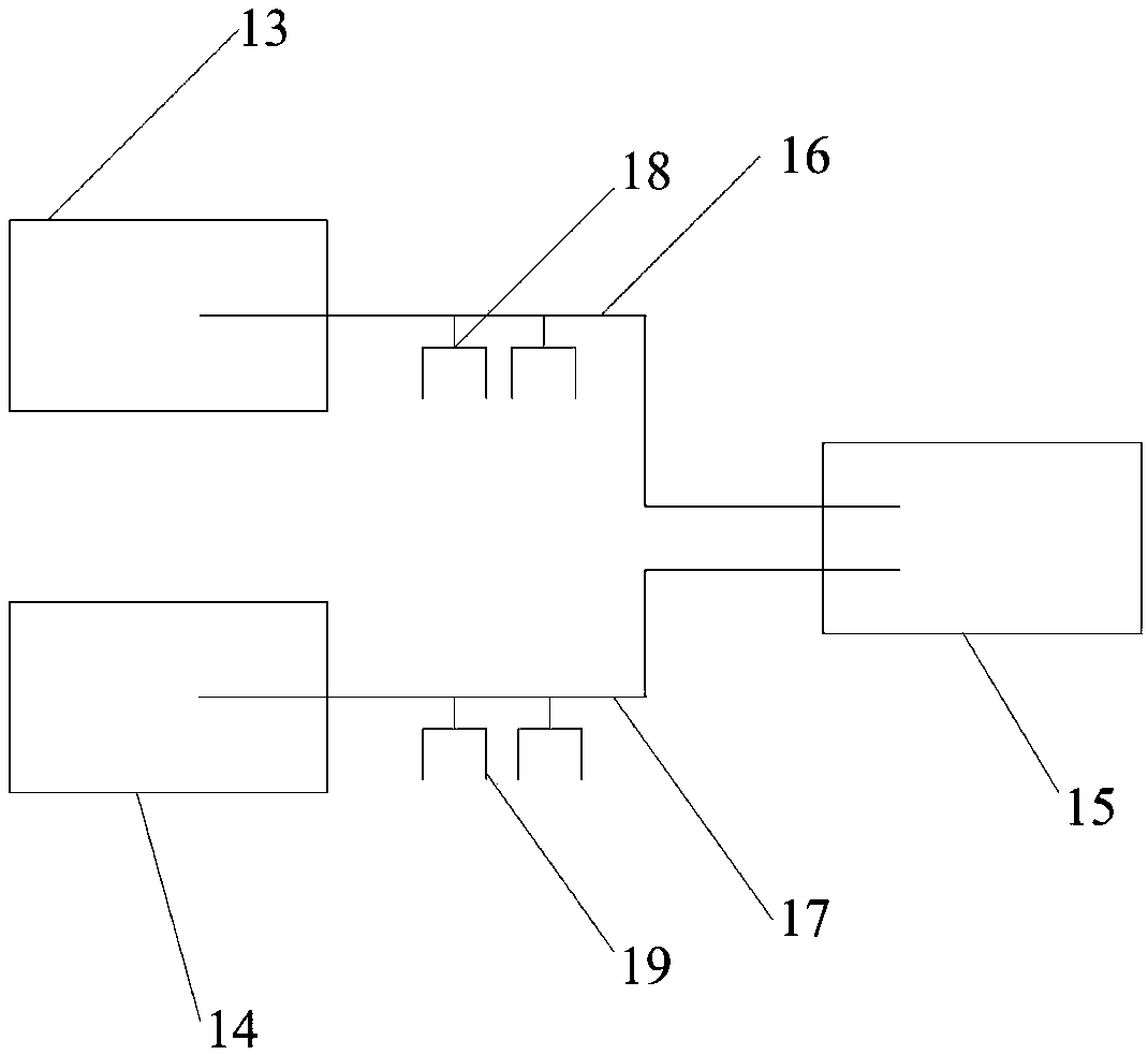
The invention discloses a catenary cantilever machining device. The catenary cantilever machining device comprises a flat cantilever machining device, an inclined cantilever machining device and a cantilever combining device; the flat cantilever machining device and the inclined cantilever machining device are arranged side by side, and the cantilever combining device is located at the tail ends of the flat cantilever machining device and the inclined cantilever machining device; the flat cantilever machining device and the cantilever combining device are connected through a flat cantilever combining manipulator truss; the inclined cantilever machining device and the cantilever combining device are connected through an inclined cantilever combining manipulator truss; the flat cantilever combining manipulator truss is used for providing a movement track for a flat cantilever combining manipulator; the inclined cantilever combining manipulator truss is used for providing a movement trackfor an inclined cantilever combining manipulator; and the cantilever combining device is used for combining a machined flat cantilever with a machined inclined cantilever. According to the catenary cantilever machining device, the machining precision and efficiency of the cantilevers can be improved.

Description

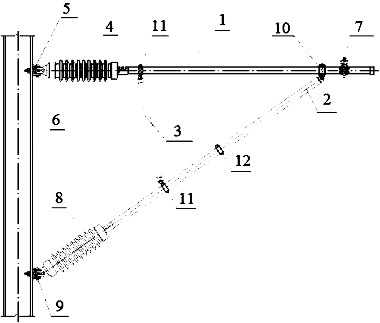
technical field [0001] The invention relates to the field of wrist arm preconfiguration processing, in particular to a contact net wrist arm processing device. Background technique [0002] The wrist arm is a new type of high-speed rail catenary support device. figure 1 The connection structure diagram when the wrist arm processed by the present invention is fixed on the pillar. see figure 1 , the flat arm tube 1, the oblique arm tube 2 and the arm support tube 3 form a triangular structure. One end of the flat arm tube 1 is fixed on the pillar 6 through the upper rod insulator 4 and the upper base 5, and the other end is installed with a load-bearing cable seat 7; one end of the oblique arm tube 2 is fixed through the lower rod insulator 8 and the lower base 9 On the pillar 6, the other end is connected to the flat arm tube 1 through the sleeve seat 10; both ends of the arm support tube 3 are respectively connected to the flat arm tube 1 and the oblique arm tube 2 throug...

Claims


Application Information

Patent Timeline
IPC IPC(8): B60M1/28B23P23/02
CPCB23P23/02B60M1/28
Inventor 韩兰贵张裔张辉周振平李爱敏李育冰李占民景建民赵印军陈建明
Owner CHINA CREC RAILWAY ELECTRIFICATION BUREAU GRP
Why Eureka
Eureka Blog
Learn More