Plate conveyer

A conveyor, plate type technology, applied in the direction of conveyor, transportation and packaging, surface pretreatment, etc., can solve the problem of increasing power source, and achieve the effect of reducing power source and improving automation

Pending Publication Date: 2018-09-28
重庆鼎赛输送机械有限公司
View PDF6 Cites 2 Cited by
  • Summary
  • Abstract
  • Description
  • Claims
  • Application Information

AI Technical Summary

Problems solved by technology

[0005] The purpose of the present invention is to provide a plate conveyor, which solves the problem of using fan drying and increasing the number of power sources in the prior art

Method used


Image

  • Plate conveyer
  • Plate conveyer
  • Plate conveyer

Examples


Embodiment 1

[0031] Embodiment one is basically as attached figure 1 , figure 2 with image 3 Shown:

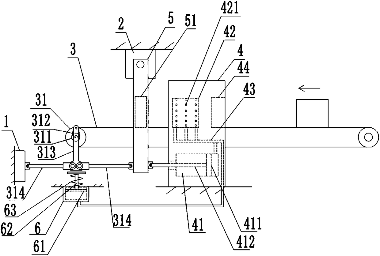
[0032] A plate conveyor, see figure 1 , including a fixed seat 1, a fixed platform 2, a conveyor body 3 and a transmission roller 31 for driving the movement of the conveyor body 3, and there are two transmission rollers, which are respectively located at the two ends of the conveyor body 3; and the conveyor body 3 The conveying roller 31 on the left side is fixed with the output end of motor. Both the fixed seat 1 and the fixed platform 2 are fixed on the wall or the ground, and the fixed platform 2 is located above the conveyor body 3 , and the fixed seat 1 is close to the output end of the conveyor body 3 .

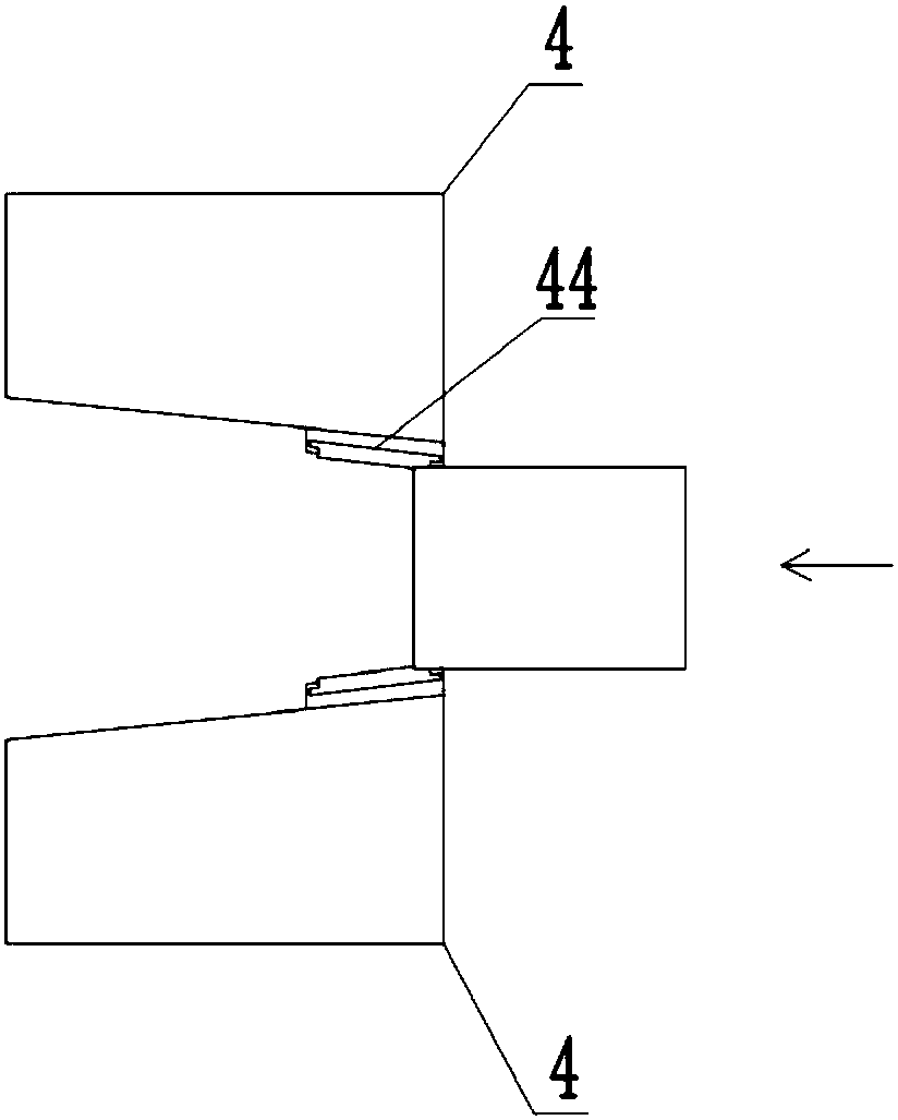
[0033] Both sides of the conveyor are provided with a drying section 4 and a swinging plate 5, and the drying section 4 and the swinging plate 5 are arranged in sequence along the conveying direction of the conveyor body 3; the drying section 4 is fixed on the ground. The up...

Embodiment 2

[0044] The difference between this embodiment and the first embodiment is that the swing plate 5 is provided with an oil cavity, and anti-rust oil is provided in the oil cavity. The upper end of the swing plate 5 is provided with an oil inlet connected to the oil chamber, and the oil inlet is provided with a plug for blocking the oil inlet; when in use, the plug can be inserted into the oil inlet. The oil cavity is provided with a through hole, and the oil-coated layer 51 is fixed with a cotton thread, and the end of the cotton thread extends into the anti-rust oil; Oil the metal surfaces on both sides of the objects in between.

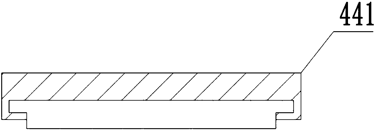
[0045] Such as Figure 4 , the detachable connection between the clamping plate 441 and the inclined surface; specifically: both sides of the clamping plate 441 are fixed with protrusions 4411, and the inclined surface is fixed with a clamping track 45 for clamping into the protrusions 4411; it is convenient to remove the clamping plate 441 from dry...


PUM


Abstract

The invention relates to the technical field of conveying, in particular to a plate conveyer. The plate conveyer comprises a fixed base, a fixed table, a conveyer body and conveying rollers; the two sides of the conveyer are each provided with a drying part and a swing plate, the drying parts and the swing plates are sequentially arranged in the conveying direction of the conveyer body, the upperends of the swing plates are hinged to the fixed table, oiling layers are fixed to the swing plates, rotating shafts are fixed to the two ends of the conveying rollers, rotating lug plates are fixed to the rotating shafts, push rods are rotatably connected to the ends of the rotating lug plates, pull rods are hinged to the two sides of the lower ends of the push rods, one pull rod is hinged to thefixed base, the other pull rod is hinged to the swing plate on the same side, an air cavity and a drying cavity are formed in each drying part, a piston is in sliding connection into each air cavity,and a piston rod is fixedly connected to each piston; the ends of the piston rods are hinged to the swing plate on the same side; multiple blowing holes are formed in the wall of the drying cavity; and a communication pipe is communicated between each drying cavity and the corresponding air cavity. The problem that in the prior art, a draught fan is added, and a power source is increased is solved.

Description

technical field [0001] The invention relates to the technical field of conveying, in particular to a plate conveyor. Background technique [0002] Apron conveyor is a conveyor that uses a series of chain plates fixed on the traction chain to transport materials in a horizontal or inclined direction. A single steel plate is hinged into a ring belt as the traction and bearing member bearing surface of the conveyor. It is composed of driving mechanism, tensioning device, traction chain, slats, driving and redirecting sprocket, frame and other parts. It has been widely used in metallurgy, coal, chemical industry, electric power, machinery manufacturing and other industrial sectors of the national economy. [0003] During the working process of the conveyor, especially in the process of transporting large objects, it is often necessary to treat the metal surfaces on both sides of the object; the processing process is: scrubbing and applying anti-rust oil to both sides of the obj...

Claims


Application Information

Patent Timeline
Patent Type & Authority Applications(China)
IPC IPC(8): B65G23/04B05C1/06B05D3/04
CPCB65G23/04B05C1/06B05D3/0406
Inventor 许璐伟
Owner 重庆鼎赛输送机械有限公司
Why Eureka
Try Eureka