Fixing device for axial fastening of diaphragm assembly
A fixed device and axial technology, applied in the field of membrane bioreactors, can solve problems affecting water purification quality, membrane swing, membrane bonding, etc., achieve good support and fixation, low cost, and prevent displacement or deformation Effect
- Summary
- Abstract
- Description
- Claims
- Application Information
AI Technical Summary
Problems solved by technology
Method used
Image
Examples
Embodiment 1
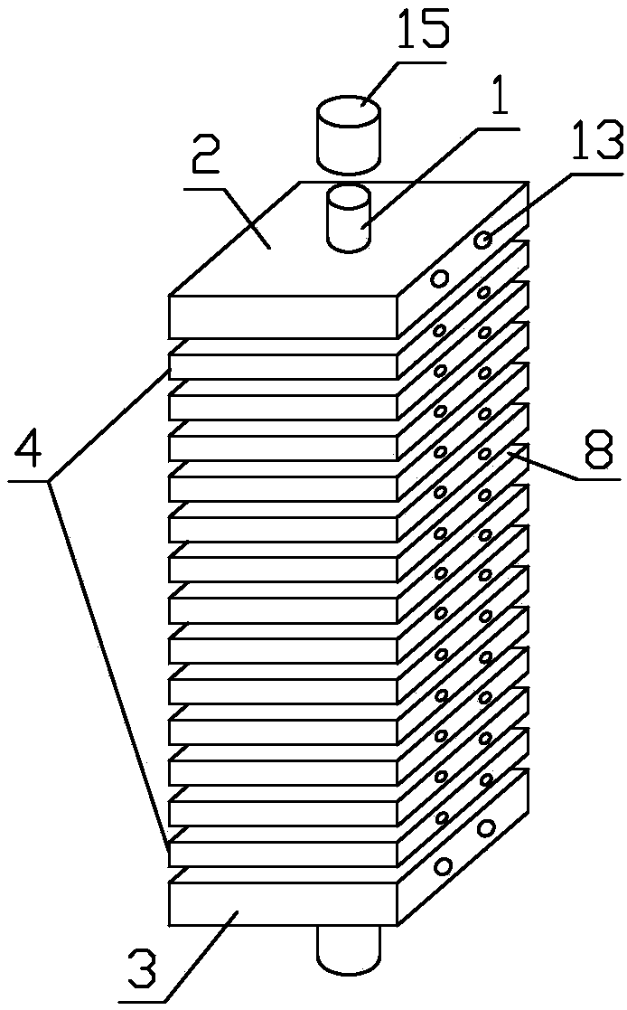
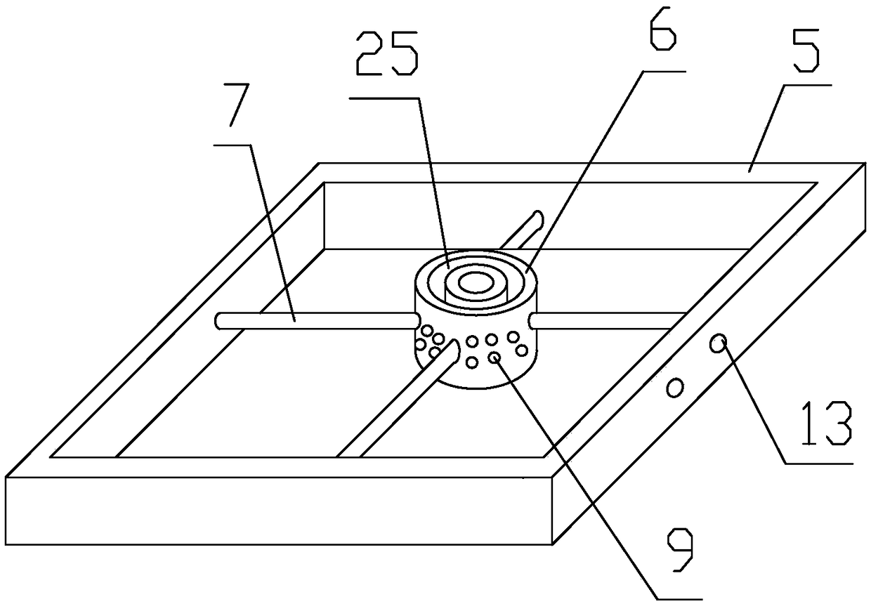
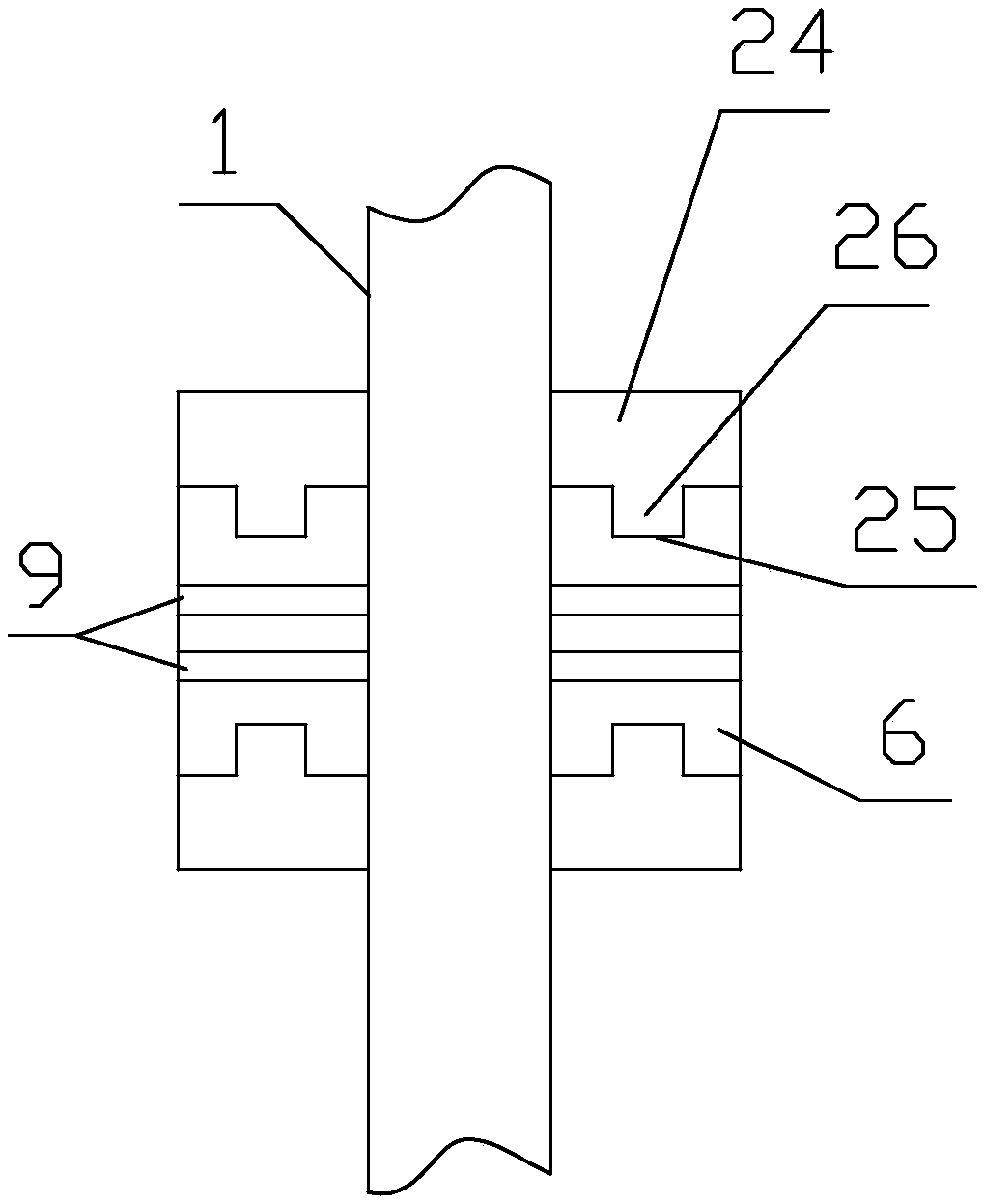
[0041] The fixing device for the axial fastening of the diaphragm assembly includes a support tube 1. Both ends in the longitudinal direction of the support tube 1 are provided with a first pressure plate 2 and a second pressure plate 3, and the first pressure plate 2 and the second pressure plate 3 are stacked A number of membrane modules 4 are provided. The membrane module includes a supporting frame 5, a connecting sleeve 6 and a filter membrane 8. The connecting sleeve 6 is sleeved outside the supporting tube 1, and the supporting frame 5 is sleeved outside the connecting sleeve 6 with clearance fit, and The outer side wall of the connecting sleeve 6 and the inner side wall of the support frame 5 are connected by a connecting rod 7. The axis of the support tube 1, the axis of the connecting sleeve 6 and the geometric center of the support frame 5 are all coincident with each other; The frame 5 and the connecting sleeve 6 are covered with filter membranes 8 at both ends in th...
Embodiment 2
[0043] Further improved on the basis of embodiment 1, two opposite outer side walls of the support frame 5 are provided with mounting holes 13, and the axial end of the adjusting rod 10 away from the adjusting ring 12 is provided with a mounting plate 14. The direction of the mounting plate 14 is It is perpendicular to the axial direction of the adjusting rod 10, the mounting plate 14 is provided with a connecting through hole, and the mounting plate 14 is fixed on the outer side wall of the support frame 5 through the connecting through hole through bolts.
Embodiment 3
[0045] On the basis of embodiment 2, a sliding groove 16 is provided on the outer side wall of the adjusting ring 12 along the circumferential direction, and the adjusting rod 12 is provided with a slider 17 adapted to the sliding groove 16 at the axial end away from the supporting frame 5 , The cross section of the sliding groove 16 and the sliding block 17 along the sliding direction are both T-shaped structures. The bottom of the sliding groove 16 is provided with a number of limit springs 18 along the circumferential direction, and a number of limit springs 18 are evenly spaced; the axial direction of the limit spring 18 is parallel to the axial direction of the threaded positioning rod 11, and the axial end of the limit spring 18 is fixed A support plate 19 is provided at the bottom and the other end of the slide groove 16; a layer of elastic connecting cloth 20 is provided in the slide groove 16 between the support plate 19 and the bottom end of the slider 17, which is ela...
PUM
 Abstract
Description
Claims
Application Information
 - R&D
- Intellectual Property
- Life Sciences
- Materials
- Tech Scout
- Unparalleled Data Quality
- Higher Quality Content
- 60% Fewer Hallucinations
Browse by: Latest US Patents, China's latest patents, Technical Efficacy Thesaurus, Application Domain, Technology Topic, Popular Technical Reports.
© 2025 PatSnap. All rights reserved.Legal|Privacy policy|Modern Slavery Act Transparency Statement|Sitemap|About US| Contact US: help@patsnap.com


