Bone-conduction microphone and method of manufacturing the same

a bone-conduction microphone and microphone technology, applied in the direction of deaf-aid sets, electrical transducers, transducer details, etc., can solve the problems of increasing the total processing period, rigidity and strength, and reducing the resonant frequency, so as to improve the yield and improve the structure. , the effect of simple structur

Inactive Publication Date: 2007-04-19
TOKIN CORP
View PDF3 Cites 5 Cited by
  • Summary
  • Abstract
  • Description
  • Claims
  • Application Information

AI Technical Summary

Benefits of technology

[0030] As mentioned above, according to the present invention, it is possible to fix a supporting portion of piezoelectric elements with a simple structure without soldering and improve a yield. Hence, an inexpensive bone-conduction microphone can be manufactured and provided with high performance and quality stabilities. That is, it is possible to provide a bone-conduction microphone including a vibration detecting part that can be assembled with a simple structure without soldering, and a method of manufacturing the same.
[0031] Further, according to the present invention, as described above, it is possible to a bone-conduction microphone that can cantilever a bimorph piezoelectric element as in the related art, can be assembled without connecting the electrode by use of a lead solder nor fixing the element to a jig and put in a high-temperature tank by use of a conductive adhesive, and can ensure a requisite holding strength and reliability in electrode connection. Accordingly, an eco-friendly material is used, and a production cost can be lowered.

Problems solved by technology

This assembly is therefore disadvantageous in that many jigs are necessary for mass-production, and the steps cannot be executed in parallel, resulting in an increase in the total processing period.
Further, a supporting rigidity depends on the conductive adhesive alone, so the rigidity and strength are insufficient in many cases, and a resonant frequency tends to be lowered.

Method used


Image

  • Bone-conduction microphone and method of manufacturing the same
  • Bone-conduction microphone and method of manufacturing the same
  • Bone-conduction microphone and method of manufacturing the same

Examples


Embodiment Construction

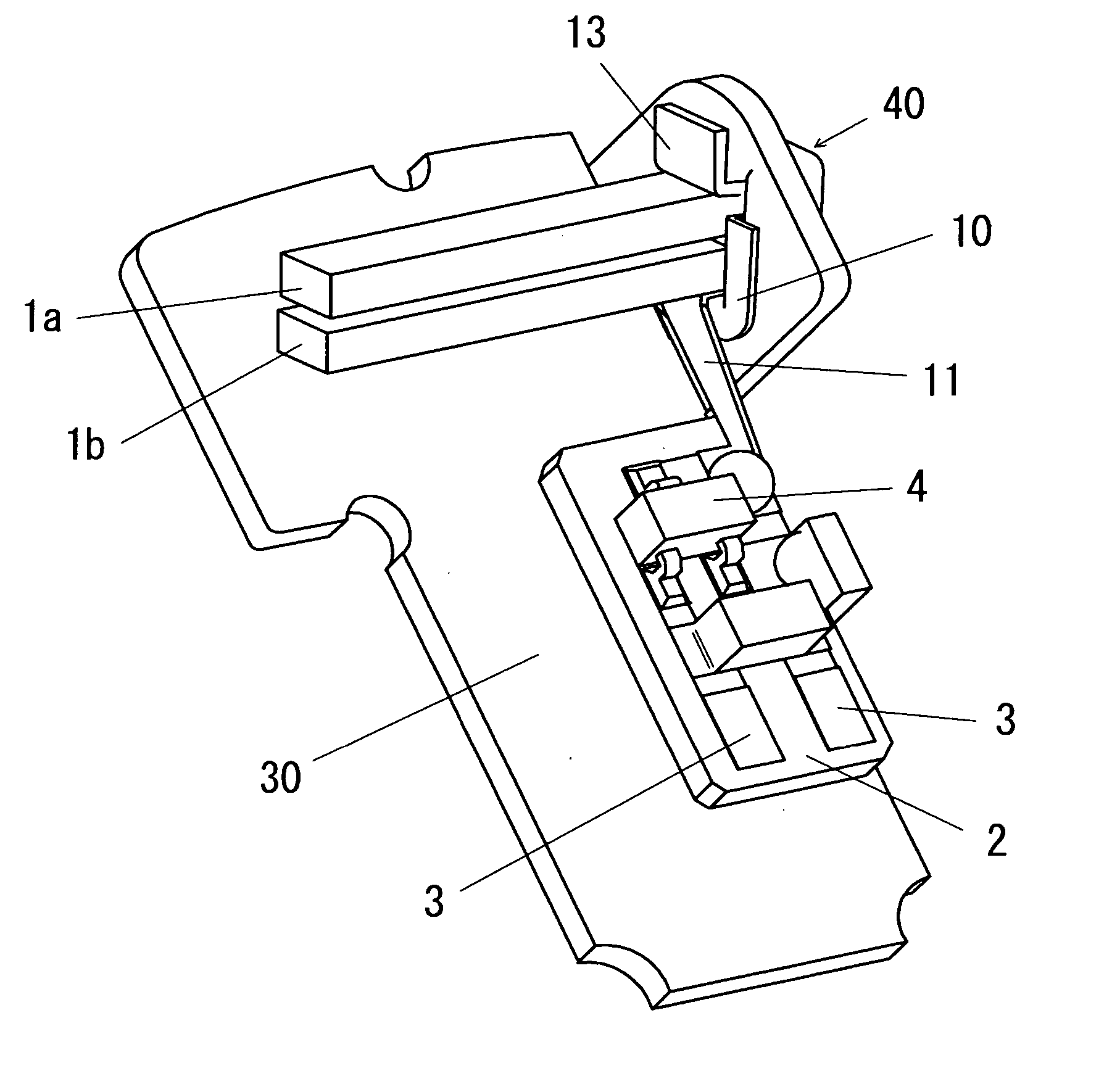
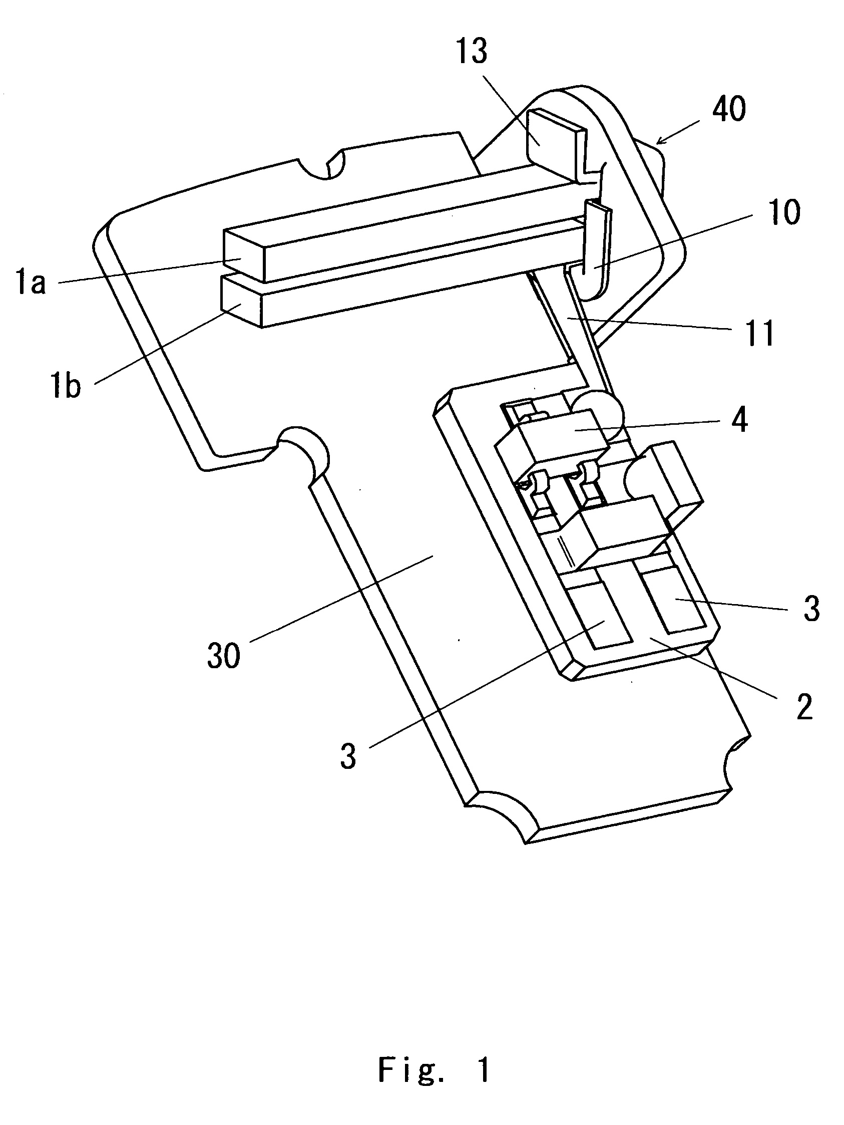
[0044] A bone-conduction microphone of an in-ear sound information transmitter according to an embodiment of the present invention has a pick-up sensor structure capable of detecting bone-conducted sounds of a low frequency to a high frequency. Thus, the most desirable structure and assembly method of a bone-conduction microphone are such structure and assembly method as do not apply extra stress or force to a piezoelectric element as an important part for detecting vibrations, and such structure and assembly method provide a stability in quality of a finished product. Hereinafter, embodiments of the present invention are described with reference to FIGS. 1 to 11.

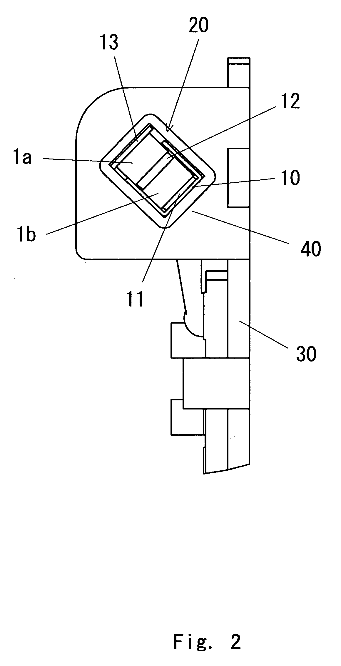
[0045]FIG. 1 is a perspective view of a bone-conduction microphone according to an embodiment of the present invention, and FIG. 2 is a right-handed side view of the bone-conduction microphone. FIG. 3 is an exploded perspective view of the bone-conduction microphone according to the embodiment of the present invention, and...


PUM


Abstract

According to an embodiment of the present invention, a piezoelectric element composing a detecting part of a bone-conduction microphone is cantilevered by being mechanically pressed into an element mounting opening of a supporting member in a microphone case while temporarily bonded to a connecting member including a signal communication spacer, a copper-made spacer, a tapered ground spacer, and an insulating spacer, and optionally reinforced and fixed by use of an adhesive. Hence, it is possible to provide a cantilevered bone-conduction microphone having a vibration detecting part that can be assembled with a simple structure by use of an eco-friendly bonding material, not a solder.

Description

BACKGROUND OF THE INVENTION [0001] 1. Field of the Invention [0002] The present invention relates to a bone-conduction microphone used in a cell phone or a mobile device, and a method of manufacturing the same. In particular, the invention relates to a bone-conduction microphone suitable as an in-ear sound information transmitter utilizing bone-conducted (voice) sound vibrations and used as accessories of the cell phone or mobile device, or suitable as a pick-up sensor for detecting a bone-conducted sound of the sound information transmitter, and to a method of manufacturing the same. [0003] Further, the present invention relates to a bone-conduction microphone for detecting bone-conducted sound vibrations and converting the vibrations into electric signals by use of a piezoelectric element. In particular, the invention relates to a bone-conduction microphone suitable for detecting vibrations of a sound conducted through the head bone and converting the vibrations into electric sign...

Claims


Application Information

Patent Timeline
Patent Type & Authority Applications(United States)
IPC IPC(8): H04R25/00
CPCH04R1/46H04R2460/13H04R2499/11
Inventor HASHIMOTO, YOICHIKAWASE, HIDEYUKIFUJITA, MASAHIKONITOBE, YUJI
Owner TOKIN CORP
Why Eureka
Try Eureka