

Motion switch
a motion switch and micro-miniature technology, applied in the direction of speed/acceleration/shock measurement, contacts, instruments, etc., can solve the problems of high accuracy of expensive semiconductor manufacturing facilities, false operation of mems, time and effort for manufacture and assembly, etc., to increase the accuracy of motion switches, facilitate header work, and facilitate the effect of deadweigh
- Summary
- Abstract
- Description
- Claims
- Application Information
AI Technical Summary
Benefits of technology
Problems solved by technology
Method used
Image

Examples
embodiment 1
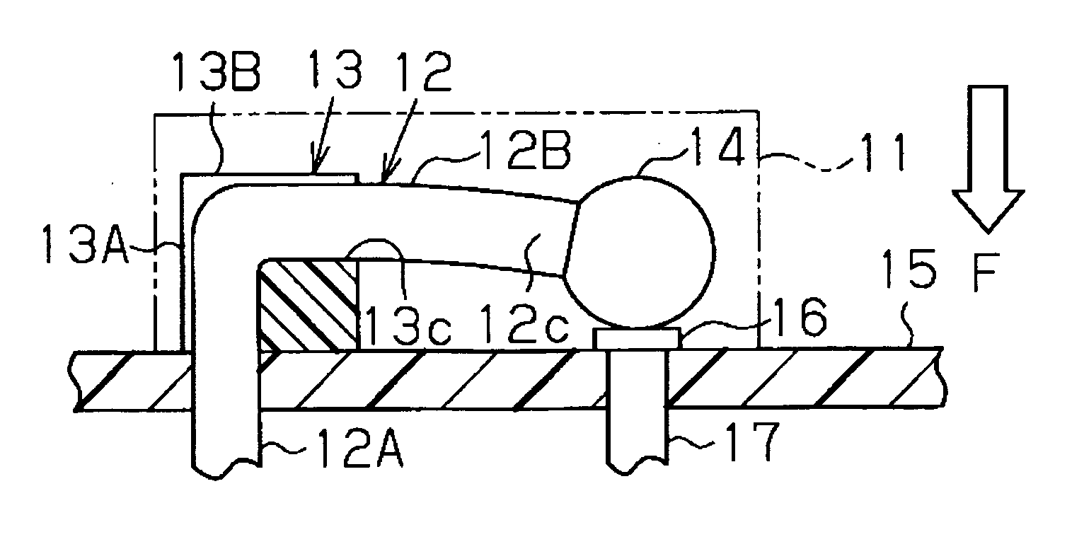
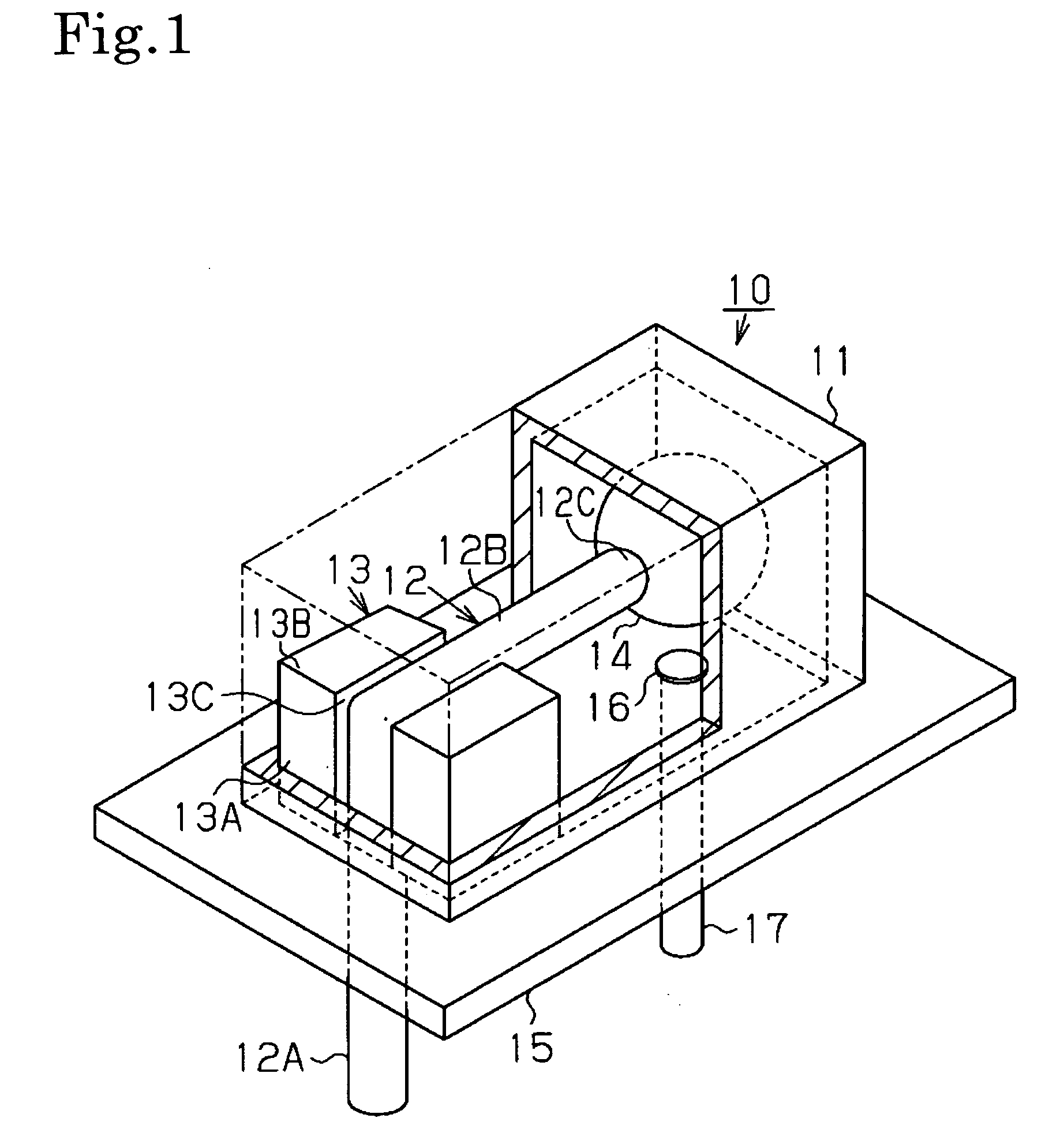
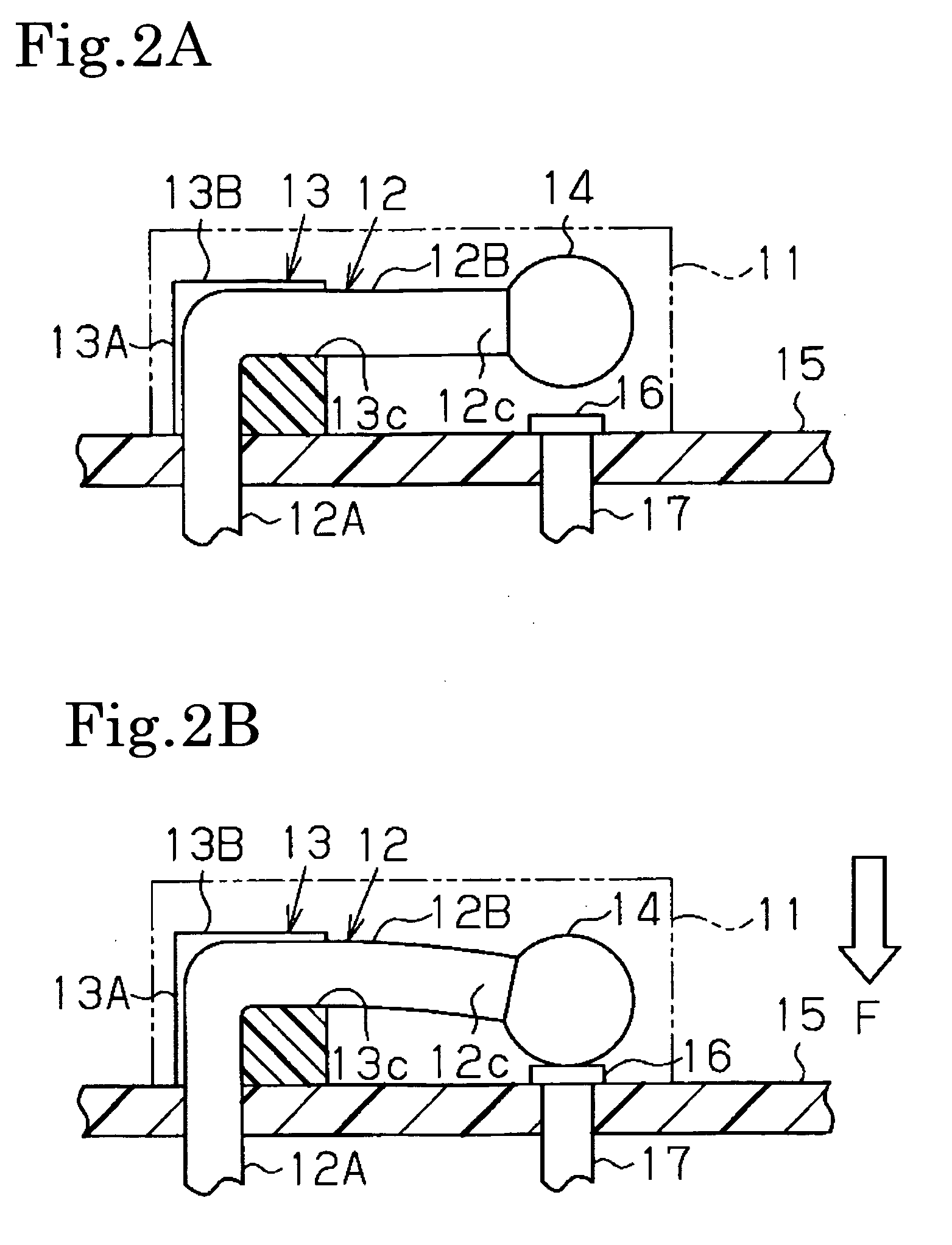
[0048]In the motion switch 10 shown in FIG. 1, by an injection molding of the polyamide 66 of 0.2 mm in thickness, the case 11 was molded in 2 mm in length, 4 mm in width, and 2 mm in height. The pedestal 13 was made of alumina, and worked to the dimensions of 1.6 mm in length, 1 mm in width and 1 mm in height, and the groove 13C was formed by applying a groove working to the base end face 13A and the upside face 13B such that the high elasticity wire 12 can be pressure-inserted. As to the high elasticity wire 12, the deadweight 14 was manufactured by header-working the SR 510 material of 0.5 mm in wire diameter φ such that the deadweight 14 contacts with the contact 16 on the board 15 with a stress (in a direction perpendicular to the high elasticity wire 12) of 33 G (G denotes a gravitational acceleration (9.8 m / s2)). Incidentally, to the surface of the deadweight 14, there was applied the gold plating in order to decrease the contact resistance.
[0049]By covering these components ...
embodiment 2
[0081]In the motion switch 20 shown in FIG. 3, by the injection molding of the polyamide 66 of 0.2 mm in thickness, the case 11 was molded in 2 mm in length, 4 mm in width, and 2 mm in height. The pedestal 23 was made of alumina, and worked to the dimension of 1.6 mm in length, 1 mm in width and 1 mm in height, and the groove 23C was formed by applying the groove working to the base end face 23A and the upside face 23B such that the high elasticity plate 22 can be pressure-inserted. As to the high elasticity plate 22, the deadweight 24 was manufactured by header-working the SR 510 material of 0.3 mm in thickness and 0.5 mm in breadth such that the deadweight 24 contacts with the contact 16 on the board 15 with the stress (in the direction perpendicular to the high elasticity plate 22) of 33 G. Incidentally, to the surface of the deadweight 24, there was applied the gold plating in order to decrease the contact resistance.
[0082]By covering these components with the cover 11 like FIG....
PUM
 Abstract
Description
Claims
Application Information