

Ditching equipment for paving discharge pipe
A sewage pipe and equipment technology, which is applied in the field of trenching equipment for laying sewage pipes, can solve the problems of slow trenching speed and uneven depth of dug trenches, and achieve fast trenching speed, uniform depth of dug trenches, The effect of improving efficiency
- Summary
- Abstract
- Description
- Claims
- Application Information
AI Technical Summary
Problems solved by technology
Method used
Image

Examples
Embodiment 1
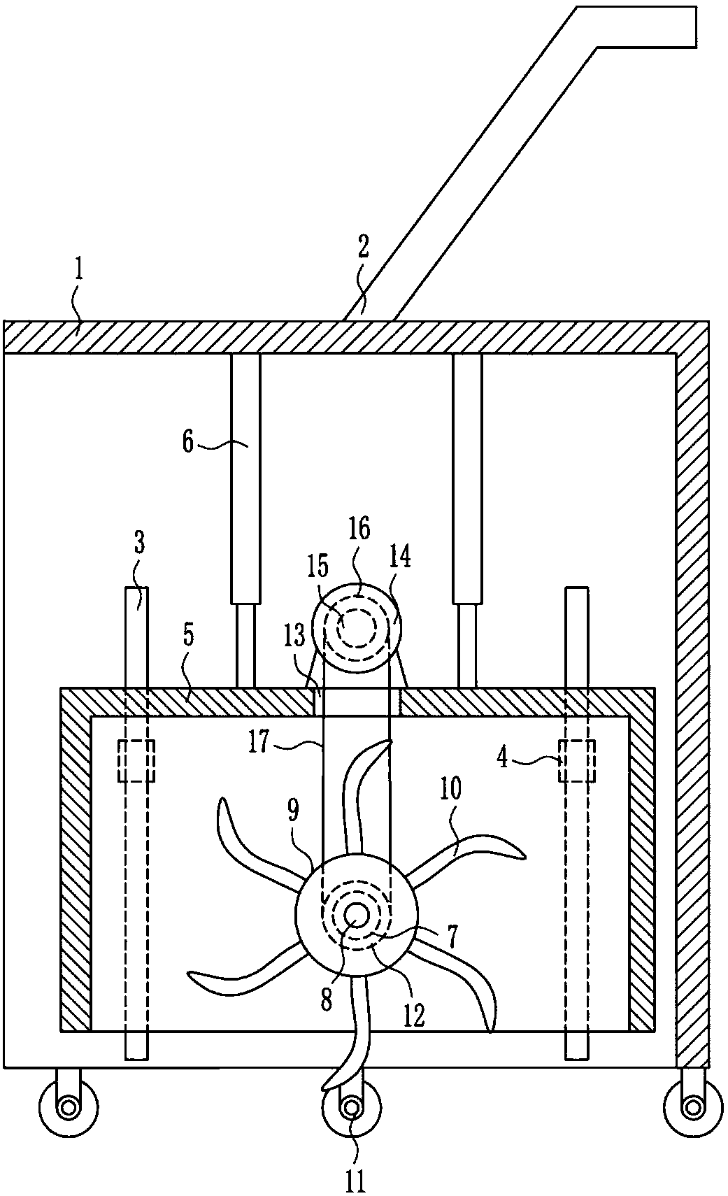
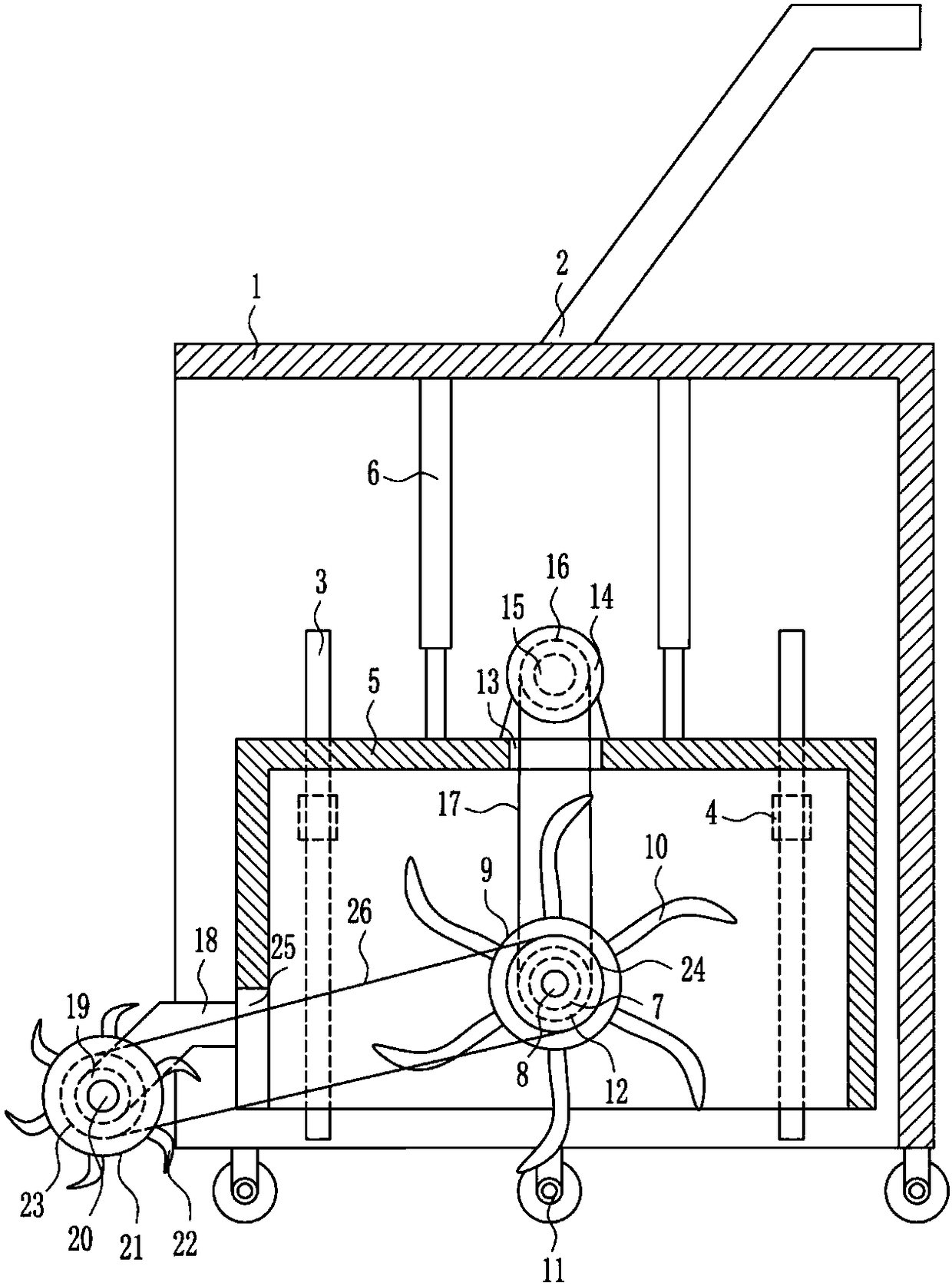
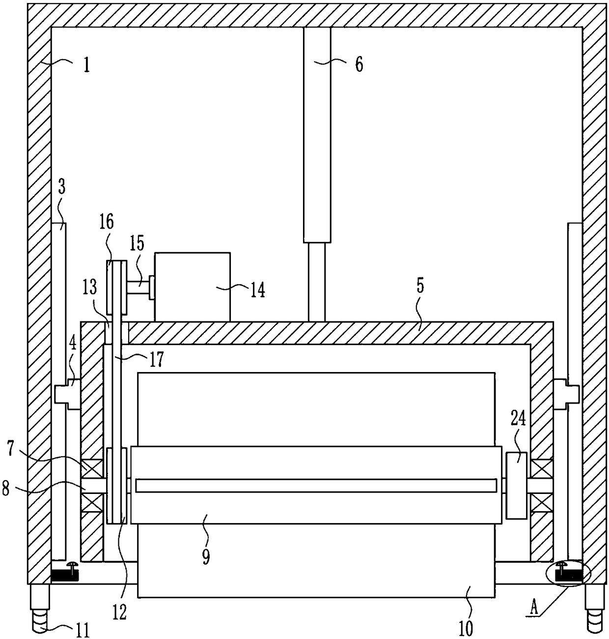
[0025] A kind of trenching equipment for laying sewage pipes, such as Figure 1-5 As shown, it includes frame 1, push handle 2, slide rail 3, slider 4, frame body 5, cylinder 6, first bearing seat 7, first rotating shaft 8, roller 9, scraper blade 10, universal wheel 11, the first One belt pulley 12, the first motor 14, the second rotating shaft 15, the second belt pulley 16 and the first flat belt 17, a push handle 2 is installed on the outer top of the frame 1, and two slide rails 3 are installed on the front and rear sides in the frame 1, and the sliding Slider 4 is provided on the inner surface of rail 3, frame body 5 is installed between front and rear sliders 4, two cylinders 6 are installed on the inner top of frame 1, and the bottom ends of telescopic rods of two cylinders 6 are connected with the outside of frame body 5. The top is connected, and the middle parts of the front and rear sides of the frame body 5 are embedded with the first bearing seat 7, and the bearin...
Embodiment 2
[0027] A kind of trenching equipment for laying sewage pipes, such as Figure 1-5 As shown, it includes frame 1, push handle 2, slide rail 3, slider 4, frame body 5, cylinder 6, first bearing seat 7, first rotating shaft 8, roller 9, scraper blade 10, universal wheel 11, the first One belt pulley 12, the first motor 14, the second rotating shaft 15, the second belt pulley 16 and the first flat belt 17, a push handle 2 is installed on the outer top of the frame 1, and two slide rails 3 are installed on the front and rear sides in the frame 1, and the sliding Slider 4 is provided on the inner surface of rail 3, frame body 5 is installed between front and rear sliders 4, two cylinders 6 are installed on the inner top of frame 1, and the bottom ends of telescopic rods of two cylinders 6 are connected with the outside of frame body 5. The top is connected, and the middle parts of the front and rear sides of the frame body 5 are embedded with the first bearing seat 7, and the bearin...
Embodiment 3
[0030] A kind of trenching equipment for laying sewage pipes, such as Figure 1-5 As shown, it includes frame 1, push handle 2, slide rail 3, slider 4, frame body 5, cylinder 6, first bearing seat 7, first rotating shaft 8, roller 9, scraper blade 10, universal wheel 11, the first One belt pulley 12, the first motor 14, the second rotating shaft 15, the second belt pulley 16 and the first flat belt 17, a push handle 2 is installed on the outer top of the frame 1, and two slide rails 3 are installed on the front and rear sides in the frame 1, and the sliding Slider 4 is provided on the inner surface of rail 3, frame body 5 is installed between front and rear sliders 4, two cylinders 6 are installed on the inner top of frame 1, and the bottom ends of telescopic rods of two cylinders 6 are connected with the outside of frame body 5. The top is connected, and the middle parts of the front and rear sides of the frame body 5 are embedded with the first bearing seat 7, and the bearin...
PUM
 Abstract
Description
Claims
Application Information