Painting device for architectural wall body

A kind of construction and wall technology, which is applied in the direction of construction and building construction, can solve the problems of prolonging working hours, slow moving speed, wall damage, etc., and achieve the effects of improving work efficiency, prolonging service life, and saving labor

Inactive Publication Date: 2018-09-28
JIANGSU BIAOLONG CONSTR GRP CO LTD
View PDF8 Cites 2 Cited by
  • Summary
  • Abstract
  • Description
  • Claims
  • Application Information

AI Technical Summary

Problems solved by technology

[0002] At present, when painting construction walls, workers need to hold the fan head and hang the paint bucket on the waist at the same time, which increases the load of the worker itself, and at the same time there is a safety hazard of the fan passing through; If the rope is hung on the side of the high-altitude wall for work, frequent repeated dipping actions will easily cause fatigue to the arms and the whole body, and in the process of moving operations, due to the heavy load, the moving speed is slow and the work is inconvenient. During the construction process, due to the constant volume of the paint, it must be replaced after a certain amount of work, which will cause damage to the walls that have been painted before, prolong the working time, and greatly reduce the work efficiency of high-altitude operations. During the painting work, due to the limited painting amount of the brush head, the painting is uneven, which affects the construction quality and effect

Method used


Image

  • Painting device for architectural wall body
  • Painting device for architectural wall body
  • Painting device for architectural wall body

Examples


Embodiment Construction

[0014] The following will clearly and completely describe the technical solutions in the embodiments of the present invention with reference to the accompanying drawings in the embodiments of the present invention. Obviously, the described embodiments are only some, not all, embodiments of the present invention. Based on the embodiments of the present invention, all other embodiments obtained by persons of ordinary skill in the art without making creative efforts belong to the protection scope of the present invention.

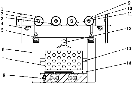
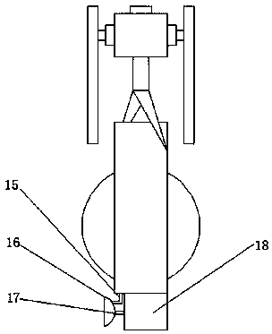
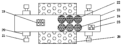
[0015] see Figure 1-3 , a kind of embodiment that the present invention provides: a kind of wall painting device for building, comprises installation frame 6, housing 23, first motor 3, second motor 11, first pulley mechanism 2, the top of storage tank 18 A feed inlet 14 is installed to facilitate the insertion of materials. A control switch 19 is installed on the surface of one side of the housing 23. The input end of the control switch 19 is electrically co...


PUM


Abstract

The invention discloses a painting device for an architectural wall body. The painting device comprises an installation frame, a shell body, a first motor, a second motor and a first belt pulley mechanism. The painting device is characterized in that a material storing groove is formed in the bottom end of the installation frame interior; a fixed wheel shaft is mounted at the top end of the material storing groove; a painting roller is mounted on the surface of the fixed wheel shaft; the shell body is mounted at the top end of the installation frame; the shell body is internally provided withthe first motor and the second motor correspondingly; an output end of the first motor is connected to a first pulley by the first belt pulley mechanism, an output end of the second motor is connectedto a second pulley by a second belt pulley mechanism; and the first pulley and the second pulley are correspondingly connected to the top end of the installation frame by ropes. Through a series of structures arranged in the painting device, in the architectural wall body painting procedure, a compound smashing mode of grinding and polishing is realized, and the smashing purpose is realized safely, quickly and efficiently.

Description

technical field [0001] The invention relates to the technical field of plastering, in particular to a wall plastering device for construction. Background technique [0002] At present, when painting construction walls, workers need to hold the fan head and hang the paint bucket on the waist at the same time, which increases the load of the worker itself, and at the same time there is a safety hazard of the fan passing through; If the rope is hung on the side of the high-altitude wall for work, frequent repeated dipping actions will easily lead to fatigue of the arms and the whole body, and in the process of moving operations, due to the heavy load, the moving speed is slow, and the work is inconvenient. During the construction process, due to the constant volume of the paint, it must be replaced after a certain amount of work, which will cause damage to the walls that have been painted before, prolong the working time, and greatly reduce the work efficiency of high-altitude ...

Claims


Application Information

Patent Timeline
Patent Type & Authority Applications(China)
IPC IPC(8): E04F21/12
CPCE04F21/12
Inventor 薛雨春冒德明冒鹏飞罗军周峰
Owner JIANGSU BIAOLONG CONSTR GRP CO LTD
Why Eureka
Try Eureka