
A special buffer device for hydraulic cylinder

A buffer device and hydraulic cylinder technology, applied in fluid pressure actuation devices, fluid pressure actuation system components, mechanical equipment, etc., can solve the problems of increasing inner wall friction, reducing sealing performance, wearing sealing rings, etc., to achieve improved The effect of oil inlet speed, reduction of oil scale formation, vibration and shock mitigation

Active Publication Date: 2020-06-12
JIANGSU KUNTAI TECH
View PDF5 Cites 0 Cited by
  • Summary
  • Abstract
  • Description
  • Claims
  • Application Information

AI Technical Summary

Problems solved by technology

[0002] The hydraulic cylinder is a common equipment in industrial production. There may not be a buffer device in the common hydraulic cylinder, but due to the huge impact force during the compression process, the speed is too fast during the descent process and a buffer is needed to prolong the use. life, but most of the existing buffer devices are not special-purpose. The special buffer devices on the market have a certain buffer effect, but because the oil contains certain impurities, it will cause its grease to regenerate, increase the friction of the inner wall, and wear the seal at the same time. ring, reducing the sealing performance, unable to resolve when the pressure is high, affecting its stability and short life

Method used


Image

  • A special buffer device for hydraulic cylinder
  • A special buffer device for hydraulic cylinder

Examples


Embodiment Construction

[0013] The following will clearly and completely describe the technical solutions in the embodiments of the present invention with reference to the accompanying drawings in the embodiments of the present invention. Obviously, the described embodiments are only some of the embodiments of the present invention, not all of them. Based on the embodiments of the present invention, all other embodiments obtained by persons of ordinary skill in the art without making creative efforts belong to the protection scope of the present invention.

[0014] The invention provides a technical solution:

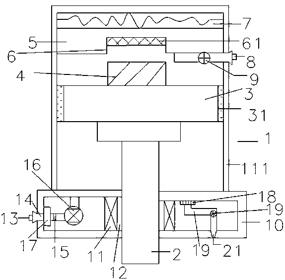
[0015] A special buffer device for a hydraulic cylinder, including a cylinder body 1, a sealing ring 111 is provided in the inner cavity of the cylinder body 1, and the sealing performance is good, a buffer plunger 2 with a rod is inserted in the cylinder body 1, and the buffer plunger 2 with a rod is connected to the piston 3. There are U-shaped sealing rings 31 at both ends of the piston 3, ...


PUM


Abstract

The invention relates to a buffer device special for a hydraulic cylinder. The buffer device comprises a cylinder body. A sealing ring is arranged in an inner cavity of the cylinder body, a rod bufferplunger is inserted in the cylinder body, the rod buffer plunger is connected with a piston, the two ends of the piston are provided with U-shaped sealing rings, the bottom of the piston is providedwith a rodless buffer plunger, the rodless buffer plunger is matched with a groove in a buffer plate at the bottom of the cylinder body, the bottom of the buffer plate is connected with a damping spring assembly, the groove is connected with a first oil guide port, the first oil guide port is provided with a one-way valve, the top of the cylinder body is provided with a cylinder cover, the joint between the cylinder cover and the rod buffer plunger is provided with a reinforcing rib, the reinforcing rib is provided with a dustproof ring, the cylinder cover is provided with a second oil guide port, the second oil guide port is connected with a needle type throttling valve through a pipeline, the needle type throttling valve is connected with a top valve through a pipeline, the stop valve isconnected with an oil filter through a pipeline, the other end of an exhaust valve is provided with an exhaust hole, and the exhaust hole is formed in the top of the cylinder cover. The structure issimple, the buffer effect is good, sealing performance is good, generated oil dirt is reduced, pressure is stable, the structure is firm, and the service life is prolonged.

Description

technical field [0001] The invention specifically relates to a special buffer device for a hydraulic cylinder. Background technique [0002] The hydraulic cylinder is a common equipment in industrial production. There may not be a buffer device in the common hydraulic cylinder, but due to the huge impact force during the compression process, the speed is too fast during the descent process and a buffer is needed to prolong the use. life, but most of the existing buffer devices are not special-purpose. The special buffer devices on the market have a certain buffer effect, but because the oil contains certain impurities, it will cause its grease to regenerate, increase the friction of the inner wall, and wear the seal at the same time. The ring will reduce the sealing performance, and it cannot be resolved under high pressure, which will affect its stability and shorten its life. Contents of the invention [0003] The object of the invention is a special buffer device for h...

Claims


Application Information

Patent Timeline
Patent Type & Authority Patents(China)
IPC IPC(8): F15B15/14F15B15/22F15B21/041
CPCF15B15/1423F15B15/1428F15B15/1433F15B15/226F15B21/041
Inventor 张树霞
Owner JIANGSU KUNTAI TECH
Learn More