
A kind of pcb lamination temperature measuring device and method

A technology of temperature measuring device and accommodating part, applied in the direction of measuring device, electric device, thermometer, etc., can solve the problems of short length, large waste, and inability to continue to use, and achieve the effect of improving efficiency and reducing consumption

Active Publication Date: 2020-02-28
DONGGUAN SHENGYI ELECTRONICS
View PDF13 Cites 0 Cited by
  • Summary
  • Abstract
  • Description
  • Claims
  • Application Information

AI Technical Summary

Problems solved by technology

[0004] In the process of PCB lamination, in order to ensure that the material temperature is in accordance with the material curing requirements, it is necessary to use a thermocouple device to measure the actual material temperature. In this process, the thermocouple wire used as a hot electrode is a consumable product. After a temperature, a certain length is pressed into the PCB, which is a big waste. As the temperature measurement progresses, it gradually becomes shorter, making it too short to continue to be used after a period of use, and must be replaced.

Method used


Image

  • A kind of pcb lamination temperature measuring device and method
  • A kind of pcb lamination temperature measuring device and method
  • A kind of pcb lamination temperature measuring device and method

Examples


Embodiment Construction

[0034] Embodiments of the present invention are described in detail below, and examples of the embodiments are shown in the drawings, wherein the same or similar reference numerals denote the same or similar elements or elements having the same or similar functions throughout. The embodiments described below by referring to the figures are exemplary and are intended to explain the present invention and should not be construed as limiting the present invention.

[0035] The technical solutions of the present invention will be further described below in conjunction with the accompanying drawings and through specific implementation methods.

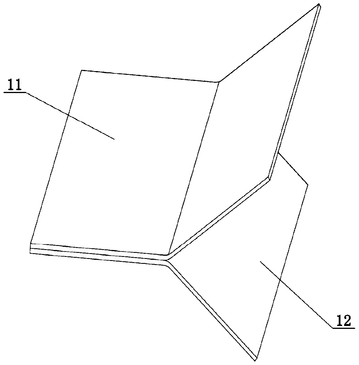
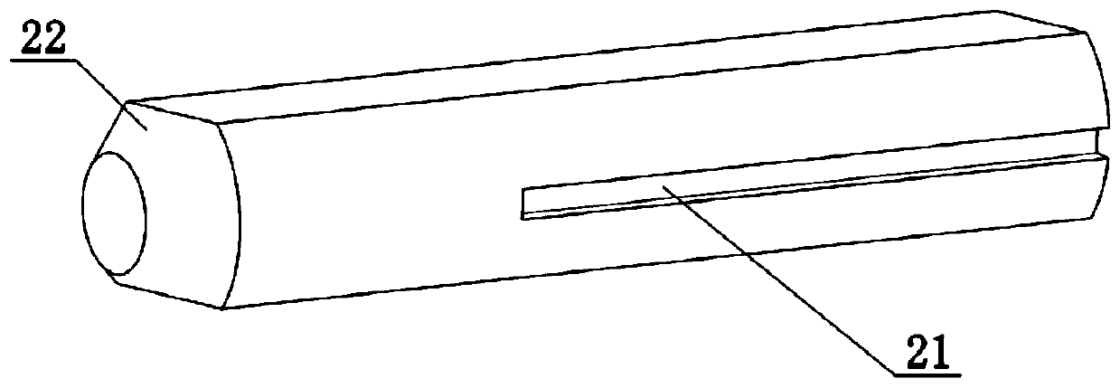
[0036] Such as Figure 1-Figure 3 As shown, the present invention provides a PCB lamination temperature measuring device, which includes a metal terminal connector 1, a metal rod 2 and a thermocouple. Among them, the metal end connector 1 is put into the PCB during temperature measurement, one end of the metal rod 2 is detachably connected ...


PUM

PropertyMeasurementUnit
thicknessaaaaaaaaaa

Abstract

The invention belongs to the technical field of PCB testing, and discloses a PCB lamination temperature measurement device and method. The PCB lamination temperature measurement device comprises a metal end connector, a metal rod and a thermocouple. One end of the metal rod is detachably connected to the metal end connector, and a thermocouple wire of the thermocouple is connected with the other end of the metal rod. The PCB lamination temperature measurement method employs the above device for temperature measurement, and comprises the following steps: A, placing the metal end connector in aPCB before the lamination of the PCB; B, enabling the metal rod connected with the thermocouple to be connected to the metal end connector, and carrying out the real-time measurement of the temperature of materials in the lamination process of the PCB; C, disassembling the metal rod from the metal end connector after the lamination of the PCB; D, carrying out the milling operation of the PCB, andremoving the metal end connector through milling. According to the invention, the setting of the metal end connector and the metal rod enables the thermocouple wire not to make direct contact with a heat source, thereby effectively protecting the thermocouple wire, and preventing the implanting of the thermocouple wire.

Description

technical field [0001] The invention relates to the technical field of PCB testing, in particular to a PCB lamination temperature measuring device and method. Background technique [0002] Thermocouple is a commonly used temperature measuring element in temperature measuring instruments. It directly measures the temperature, and converts the temperature signal into a thermal electromotive force signal, and converts it into the temperature of the measured medium through an electrical instrument (secondary instrument). The shapes of various thermocouples are often very different due to needs, but their basic structures are roughly the same, usually composed of main parts such as thermal electrodes, insulating sleeve protection tubes, and junction boxes, and are usually associated with display instruments, recording instruments, and electronic regulators. used together with the device. [0003] PCB (Printed Circuit Board), the Chinese name is printed circuit board, as a suppor...

Claims


Application Information

Patent Timeline
Patent Type & Authority Patents(China)
IPC IPC(8): G01K7/02G01K1/08
CPCG01K1/08G01K7/02
Inventor 万里鹏刘梦茹纪成光王祥
Owner DONGGUAN SHENGYI ELECTRONICS
Learn More