
A portable tensile stress electrochemical corrosion device for metal materials

A technology of stress corrosion and tensile stress, applied in measuring devices, analysis materials, weather resistance/light resistance/corrosion resistance, etc., can solve the problems of small corrosion area, tensile stress corrosion, and shape limitation of tensile specimens, etc., to achieve The effect of simple operation, accurate result analysis and convenient loading

Active Publication Date: 2021-05-14
NANJING INST OF TECH
View PDF8 Cites 0 Cited by
  • Summary
  • Abstract
  • Description
  • Claims
  • Application Information

AI Technical Summary

Problems solved by technology

[0005] In existing patents, CN101498649A (portable metal material tensile stress corrosion device and method thereof), its disadvantage is that it is limited to sheet-like tensile samples, the corrosion area is relatively small, and the electrochemical part is not perfect enough, CN104007058A (a Portable metal wire tensile stress corrosion experimental device) relates to the preparation method of stress corrosion electrochemical device, which is only applicable to wire tensile
In addition, CN2593182Y (portable tensile stress corrosion test device) involves the manufacture of stress corrosion tensile equipment and adds springs to replace the levers and weights in the original laboratory. It does not involve electrochemical devices, and the crack monitoring device cannot accurately detect tension. Tensile specimen fracture
Existing equipment is only suitable for tensile stress corrosion that does not involve electrochemical devices, or the shape of tensile samples is relatively limited, and the performance is not perfect

Method used


Image

  • A portable tensile stress electrochemical corrosion device for metal materials
  • A portable tensile stress electrochemical corrosion device for metal materials
  • A portable tensile stress electrochemical corrosion device for metal materials

Examples


Embodiment Construction

[0022] A further detailed description will be made below in conjunction with the accompanying drawings.

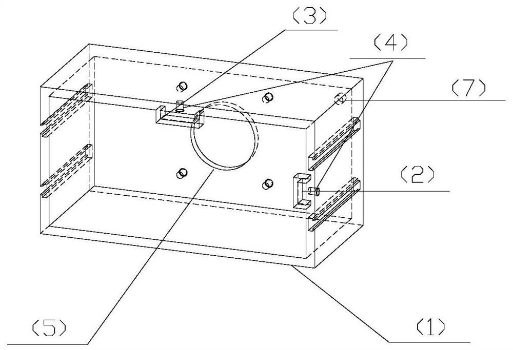
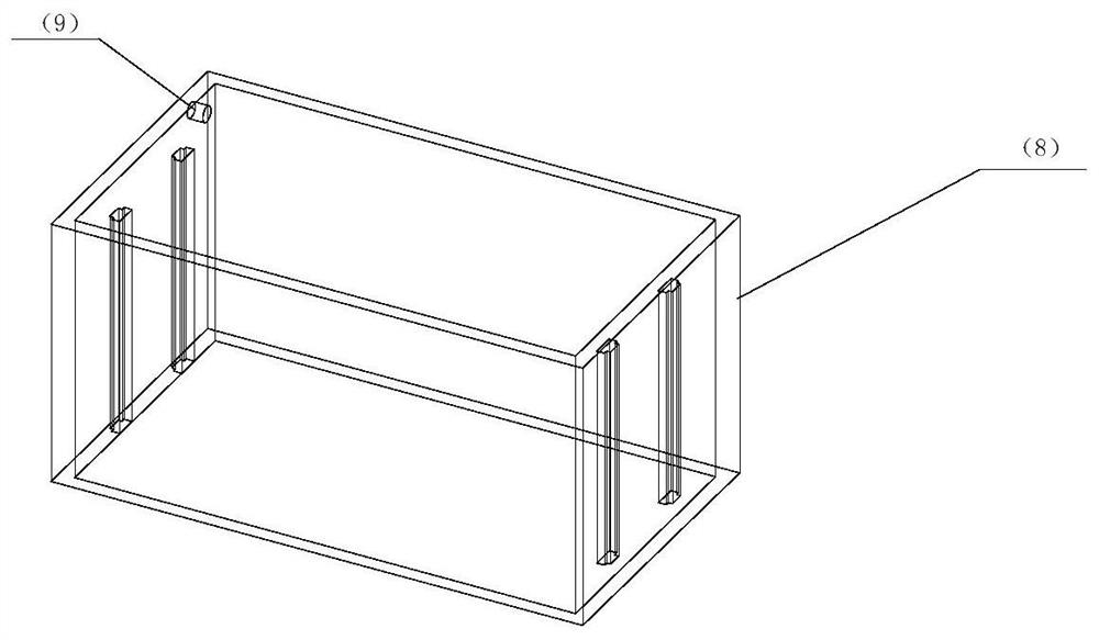
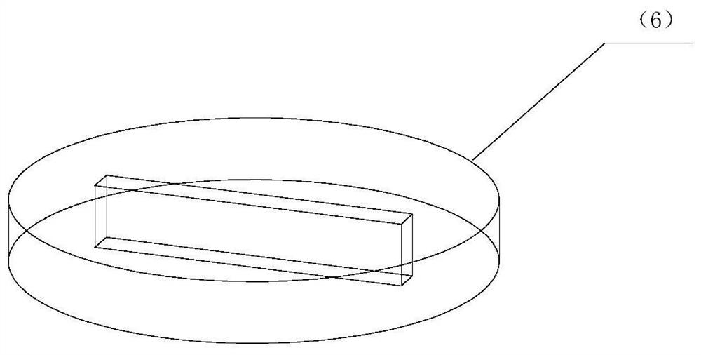
[0023] As shown in the figure, the structural components of a metal material tensile stress electrochemical corrosion tank device are mainly composed of (1) stress corrosion container (2) platinum electrode tank (3) calomel electrode tank (4) plastic fastening screws (Rubber gaskets can be added to prevent liquid leakage) (5) columnar test tank (7) composed of corrosion liquid injection holes.

[0024] Its installation process shows:

[0025] 1. Fix the sample through the fixture of the tensile testing machine to ensure that the tensile force on the sample is at the same level, and select a suitable test tank according to the shape and size of the sample. According to the height limit of the liquid tank device and the screw, the sample selection range is 50mm≤L≤1000mm.

[0026] 2. Connect (1) the stress corrosion container with the tensile testing machine through four sc...


PUM


Abstract

The invention discloses a metal material tensile stress electrochemical corrosion liquid tank device and a method thereof. The corrosion test tank is a transparent cuboid acrylic expandable box without a cover, and the corrosion test tank is a transparent cuboid acrylic box without a cover. The telescopic box is connected with the top of the fixture through a screw. Samples with different gauge lengths can adjust the height of the liquid pool by sliding between the casing and the liquid tank. There is a hole at the bottom of the liquid pool. With accessories, stress corrosion experiments on samples of different shapes can be realized. In addition, the box body has corrosive liquid injection holes and output holes, which can realize dynamic changes in the corrosive environment. The novel corrosive liquid tank device and method provided by the present invention realize in-situ electrochemical and tensile performance detection under the stress-erosion-corrosion coupling effect of tensile samples of different shapes and sizes, and are easy to disassemble, easy to clean, and faster Accurately provide test results, eliminate sample size limitations, reduce process re-optimization costs, and improve production efficiency.

Description

technical field [0001] The patent of the present invention relates to a metal tensile stress electrochemical corrosion liquid tank experimental device for studying the stress corrosion resistance of materials in natural or specific environments. Background technique [0002] Stress corrosion refers to the damage caused by the metal in a specific corrosive medium under the action of tensile stress. Stress corrosion research is an important field of safety and reliability research. At present, there are three commonly used methods to study stress corrosion: constant deformation stress corrosion test method, constant load stress (including smooth specimen and notched specimen) corrosion test method and prefabricated crack specimen stress corrosion test method. Among them, the constant deformation stress corrosion test method and the prefabricated crack specimen stress corrosion test method can be completed without equipment, while the constant load smooth tensile stress corros...

Claims


Application Information

Patent Timeline
Patent Type & Authority Patents(China)
IPC IPC(8): G01N17/02
CPCG01N17/006G01N17/02
Inventor 张振李桂珍熊桑余飞海王琪包晓燕吴明辉姚猛
Owner NANJING INST OF TECH
Learn More