Power equipment on-site real-time monitoring alarm device and control method

A technology of real-time monitoring and alarm equipment, applied in the direction of measuring electricity, measuring devices, measuring electrical variables, etc., to achieve the effect of improving electricity saving, promoting intensive utilization, and saving space

Inactive Publication Date: 2018-09-28
STATE GRID HEBEI ELECTRIC POWER CO LTD
View PDF7 Cites 3 Cited by
  • Summary
  • Abstract
  • Description
  • Claims
  • Application Information

AI Technical Summary

Problems solved by technology

At present, for household and industrial electrical equipment, usually only an electric energy meter for metering electricity charges is set on the bus, and it is impossible to realize real-time monitoring and alarm of many electrical equipment on site

Method used


Image

  • Power equipment on-site real-time monitoring alarm device and control method
  • Power equipment on-site real-time monitoring alarm device and control method

Examples


Embodiment 1

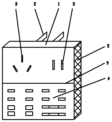
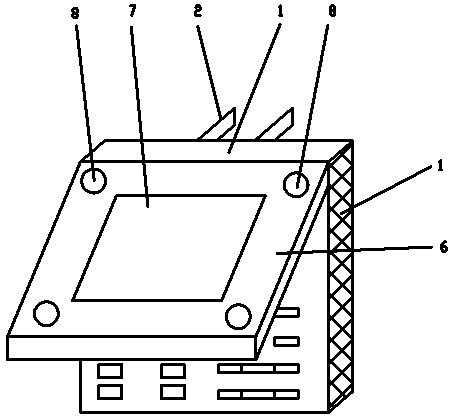
[0026] Referring to the accompanying drawings, the real-time monitoring and alarming equipment for electric power equipment of the present invention includes a monitoring box 1 and a power consumption measurement chip arranged in the monitoring box 1 in its structure, and a power plug 2 for connecting to a power supply is arranged on the ventral surface of the monitoring box 1 On the back of the monitoring box 1, an electrical jack 3 for connecting electrical equipment is arranged, wherein the power plug 2 includes a two-pole power plug and a three-pole power plug, and the electrical jack 3 includes a two-pole electrical jack and a three-pole power plug. Type electrical jack; the input panel 4 for inputting the power consumption alarm threshold is set under the back of the monitoring box 1; an insulating partition 9 is set between the electrical jack 3 and the input panel 4; the input panel 4 adopts a button keyboard, and the button keyboard At least a threshold value setting i...

Embodiment 2

[0028] The control method for on-site real-time monitoring and alarming equipment of electric power equipment of the present invention comprises the following steps:

[0029] A. Turn on the wireless router and the wireless network card of the monitoring box 1 to keep the wireless communication unblocked;

[0030] B. Plug the power plug 2 of the monitoring box 1 into the power socket, and at the same time plug the power plug of the electrical appliance into the electrical socket 3 of the monitoring box 1, and input the corresponding electrical name in the equipment selection area of ​​the input panel 4 , and at the same time, enter the electricity consumption monitoring threshold information of the electrical appliance in the threshold setting input area of ​​the input panel 4, including the unit electricity consumption threshold and the cumulative electricity consumption threshold;

[0031] C. The microprocessor automatically checks the code according to the name of the electr...


PUM


Abstract

The invention discloses a power equipment on-site real-time monitoring alarm device and control method. The device comprises a monitoring box and a measuring chip which is arranged in the monitoring box and used for measuring power consumption, a power plug connected with a power supply is arranged on a ventral surface of the monitoring box, an electric appliance jack connected with power equipment is formed in the upper portion of the back of the monitoring box, and an input panel for inputting power consumption alarm threshold values is arranged at the back of the monitoring box. A box coveris hinged onto the monitoring box, a visual alarm and a display screen for displaying power consumption information are arranged on the box cover, and an audible alarm is arranged on the side face ofthe monitoring box. The device overcomes the shortcomings of the prior art, abnormal power consumption conditions of various types of power equipment can be subjected to real-time monitoring, audibleand visual alarm and remote control.

Description

technical field [0001] The invention relates to the technical field of electricity consumption measurement, in particular to an on-site real-time monitoring and alarming device for electric power equipment and a control method thereof. Background technique [0002] People's lives have already entered the era of electrification, and various electrical equipment has become a necessity of people's life. With the massive and excessive consumption of energy, the intensive use of energy has become an engineering cause that concerns the whole society. At present, for household and industrial electrical equipment, usually only an electric energy meter for metering electricity charges is set on the bus, and it is impossible to realize real-time monitoring and alarm of many electrical equipment on site. Contents of the invention [0003] The technical problem to be solved by the present invention is to overcome various deficiencies in the prior art, and provide a real-time monitori...

Claims


Application Information

Patent Timeline
Patent Type & Authority Applications(China)
IPC IPC(8): G01R1/04G01R31/00
CPCG01R1/04G01R31/00
Inventor 杜娟
Owner STATE GRID HEBEI ELECTRIC POWER CO LTD
Why Eureka
Try Eureka