Digital display high-sensitivity conductivity and high-resistance resistivity measuring circuit and method
A high-sensitivity, resistance measurement technology, applied in conductance and high-resistance resistance measurement circuits, measuring ultra-high-value resistance, and measuring conductance and high-resistance resistance in pure resistance lines, it can solve the problem of large time constant of RC input circuit filter , low jump count instability, loss of practical significance, etc., to achieve the effect of simple structure, improved accuracy, and convenient conversion
- Summary
- Abstract
- Description
- Claims
- Application Information
AI Technical Summary
Problems solved by technology
Method used
Image
Examples
Embodiment 1
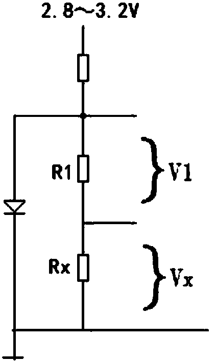
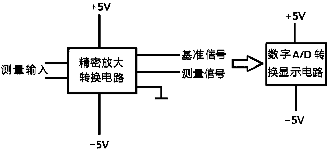
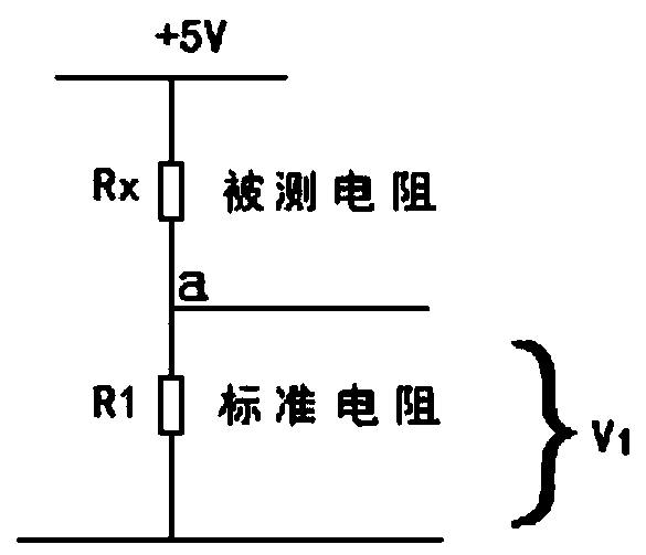
[0096] Embodiment 1, digital display high-sensitivity conductance and high-resistance resistance measurement circuit (this specification is referred to as conductance and high-resistance resistance measurement circuit), such as Figure 1-14 As shown, it includes a measurement circuit connected in sequence, a precision amplification conversion circuit and a digital A / D conversion display circuit. The measurement circuit sends the voltage signal of the measured resistance to the precision amplifying conversion circuit, and the precision amplifying conversion circuit performs impedance conversion and resistance voltage division, and adjusts it to a voltage capable of measuring the resistance by the ratio method. The precision amplification conversion circuit sends the adjusted reference voltage and measurement signal voltage to the digital A / D conversion display circuit, and the digital A / D conversion display circuit converts them into corresponding display values for display. ...
Embodiment 2
[0178] Embodiment 2. The impedance conversion circuit in Embodiment 1 is changed from a non-inverting voltage follower circuit to an inverse proportional operation circuit.
[0179] Such as Figure 9 As shown, the specific connection mode of the conductance and high-value resistance measurement circuit in this embodiment is as follows:
[0180] The measurement circuit is still composed of R1 and Rx connected in series. In this embodiment, one end of Rx is connected to the measurement voltage V+, and the other end is connected to R1. One end of R1 is connected to Rx, and the other end is connected to the output end of the impedance transformation circuit. The connection point between Rx and R1 is point a.
[0181] The impedance transformation circuit consists of an operational amplifier and a set of diodes connected in antiparallel to each other (such as Figure 9 As shown in the protection diodes D1 and D2), the group of diodes connected in antiparallel to each other is con...
PUM
 Abstract
Description
Claims
Application Information
 - R&D
- Intellectual Property
- Life Sciences
- Materials
- Tech Scout
- Unparalleled Data Quality
- Higher Quality Content
- 60% Fewer Hallucinations
Browse by: Latest US Patents, China's latest patents, Technical Efficacy Thesaurus, Application Domain, Technology Topic, Popular Technical Reports.
© 2025 PatSnap. All rights reserved.Legal|Privacy policy|Modern Slavery Act Transparency Statement|Sitemap|About US| Contact US: help@patsnap.com


