
FPGA-based linear frequency modulation signal generating device with adjustable parameters and its generating method

A chirp signal and parameter technology, which is used in measurement devices, radio wave measurement systems, and radio wave reflection/re-radiation, etc. problems, to achieve the effect of supporting flexible adjustment of parameters, reducing resource utilization, and facilitating real-time input

Active Publication Date: 2022-03-22
XIDIAN UNIV
View PDF16 Cites 0 Cited by
  • Summary
  • Abstract
  • Description
  • Claims
  • Application Information

AI Technical Summary

Problems solved by technology

[0003] The traditional method of generating linear frequency modulation signals mainly relies on the analog circuit method. Due to the disadvantages of the analog circuit method, such as difficult design, long development cycle, single signal waveform, and difficulty in realizing a signal waveform with a high degree of frequency modulation, etc., it greatly limits the radar real-time Improvement of Signal Processor System Performance
[0004] With the continuous development of digital technology, since the direct digital frequency synthesis (DDS) technology was first proposed by the American J. Tierncy in 1971, the use of DDS technology to synthesize pulsed chirp signals has been highly valued by people and has been widely used; in recent years In the past, the platform equipped with a special DDS chip can generate a stable chirp signal, but the platform has a long construction period, is difficult to develop, and is not easy to program. These shortcomings have increased the difficulty of generating chirp signals.

Method used


Image

  • FPGA-based linear frequency modulation signal generating device with adjustable parameters and its generating method
  • FPGA-based linear frequency modulation signal generating device with adjustable parameters and its generating method
  • FPGA-based linear frequency modulation signal generating device with adjustable parameters and its generating method

Examples


Embodiment Construction

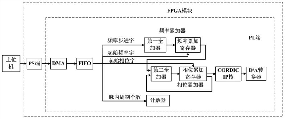
[0052] refer to figure 1 , is a block diagram of an FPGA-based parameter-adjustable chirp signal generating device of the present invention; wherein, the FPGA-based parameter-adjustable chirp signal generating device includes a host computer and an FPGA module, and the FPGA module It includes a PS terminal and a PL terminal, and the PL terminal includes a direct memory access controller (DMA controller), a frequency accumulator, a phase accumulator, a counter, a CORDIC core and a digital-to-analog converter, and the frequency accumulator includes a first full An adder and a frequency accumulation register, the phase accumulator includes a second full adder and a phase accumulation register, the first full adder and the second full adder are respectively N-bit full adders; N is 20 in this embodiment.

[0053] The first full adder comprises a first input terminal, a second input terminal and a first output terminal, and the frequency accumulation register comprises a third input...


PUM


Abstract

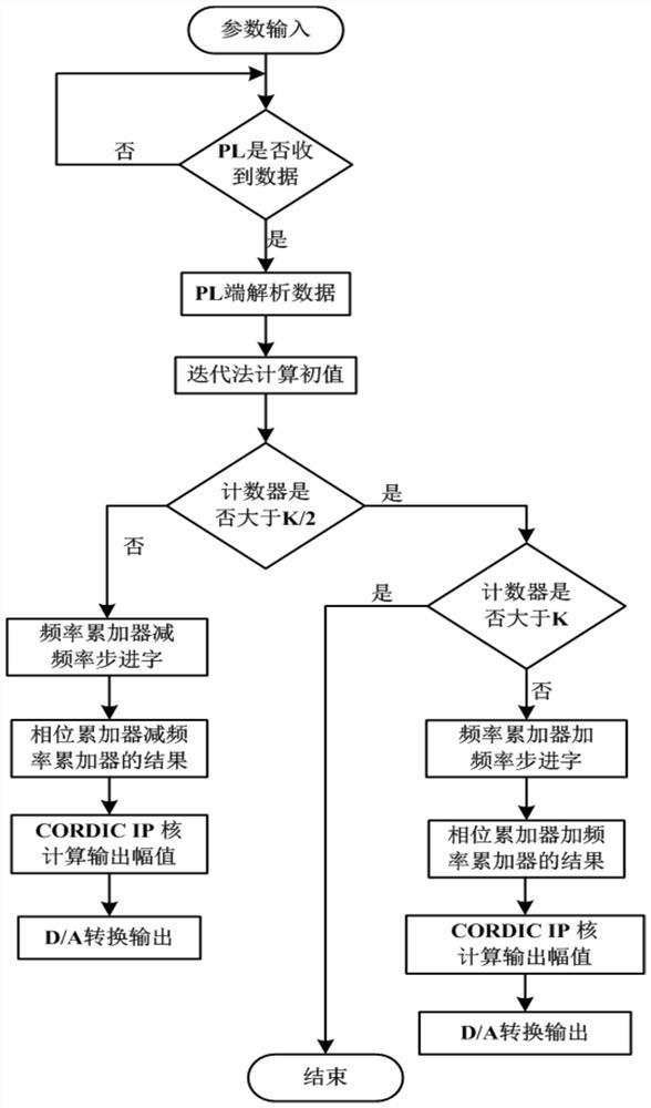
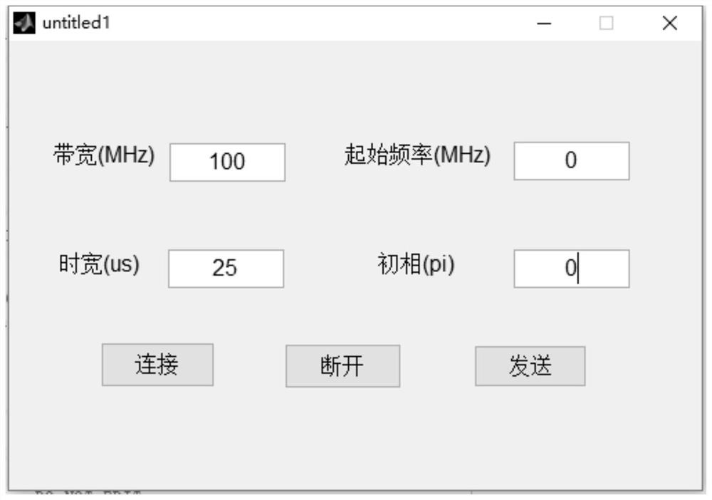
The invention discloses a linear frequency modulation signal generator with adjustable parameters based on FPGA. The idea is: the host computer obtains four parameters, and the PS terminal obtains the step frequency word △FW, the initial frequency word FW, the initial frequency word according to the four parameters. The phase word PW and the number of clock cycles K in the pulse; the frequency accumulation register sends FW to the first full adder and adds it to △FW to obtain the frequency addition result; the DMA controller controls to send △FW to the first full adder The control sends FW to the frequency accumulation register, the control sends PW to the phase accumulation register, and the control sends K to the counter; the phase accumulation register sends PW to the second full adder and adds the result of the frequency addition, Obtain the phase addition result; the CORDIC IP core calculates the amplitude value of the chirp signal according to the phase accumulation result; the D / A converter converts the amplitude value of the chirp signal into an analog signal of the chirp signal; the counter determines the chirp according to K The number of analog signal generation times for the signal.

Description

technical field [0001] The invention belongs to the technical field of digital signal processing, and in particular relates to an FPGA-based parameter-adjustable linear frequency modulation signal generating device and a generating method thereof, which are suitable for the design of a radar real-time signal processing system. Background technique [0002] Since the end of the 1950s, with the improvement of the performance of the radar real-time signal processing system, increasingly stringent requirements have been put forward for the effective range, measurement accuracy and distance resolution of the radar; in order to solve the problems of the range and resolution, Pulse compression technology and linear frequency modulation signal came into being; the linear frequency modulation signal can obtain very high distance resolution and radial velocity resolution after pulse compression because its time-width bandwidth product is much greater than 1, so the linear frequency mod...

Claims


Application Information

Patent Timeline
Patent Type & Authority Patents(China)
IPC IPC(8): G01S13/26G01S7/282
CPCG01S7/282G01S13/26
Inventor 梁毅李昕卓丁金闪范家赫
Owner XIDIAN UNIV
Learn More