SD card system applied to server mainboard and design method of SD card system

A design method and server technology, applied in the direction of instrumentation, electrical digital data processing, etc., can solve the problems of unfavorable server board device density, large server board space, etc.

Inactive Publication Date: 2018-09-28
ZHENGZHOU YUNHAI INFORMATION TECH CO LTD
View PDF5 Cites 1 Cited by
  • Summary
  • Abstract
  • Description
  • Claims
  • Application Information

AI Technical Summary

Problems solved by technology

[0005] This application provides an SD card system and its design method applied to the mainboard of the server to solve the problem that the SD card module occupies a large space on the mainboard of the server in the prior art, which is not conducive to improving the device density of the mainboard of the server

Method used


Image

  • SD card system applied to server mainboard and design method of SD card system
  • SD card system applied to server mainboard and design method of SD card system
  • SD card system applied to server mainboard and design method of SD card system

Examples


Embodiment 1

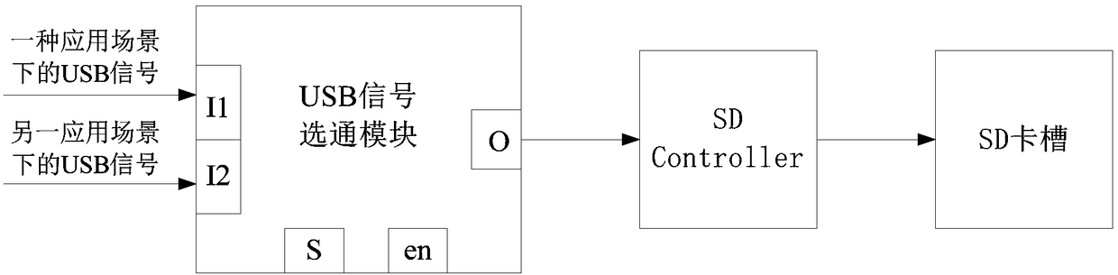
[0033] see figure 2 , figure 2 It is a schematic structural diagram of an SD card system applied to a server motherboard provided by the embodiment of the present application. Depend on figure 2It can be seen that the SD card system applied to the mainboard of the server provided by this application mainly includes three parts: a USB signal gating module, an SD Controller and an SD card slot. Wherein, the USB signal gating module includes at least two input terminals and one output terminal, the input terminals are used to receive USB signals of different application scenarios, and the output terminals are connected to SDController and SD card slot in turn.

[0034] In the present application, the USB signal gating module is used to selectively turn on the input terminal matching the output terminal after receiving the USB signal. Determining the input terminal according to the customer requirements of the output terminal is equivalent to determining the USB signal to be...

Embodiment 2

[0048] exist figure 2 and image 3 On the basis of the illustrated embodiment see Figure 4 , Figure 4 It is a schematic flowchart of a design method of a server motherboard SD card system provided by the embodiment of the present application. Depend on Figure 4 As can be seen, the design method of the server motherboard SD card system in the present application mainly includes:

[0049] S1: Install a USB signal gating module on the main board of the server, so that USB signals applied in different scenarios are transmitted to the SD Controller through the USB signal gating module.

[0050] S2: Use the USB signal gating module to selectively conduct the USB signal.

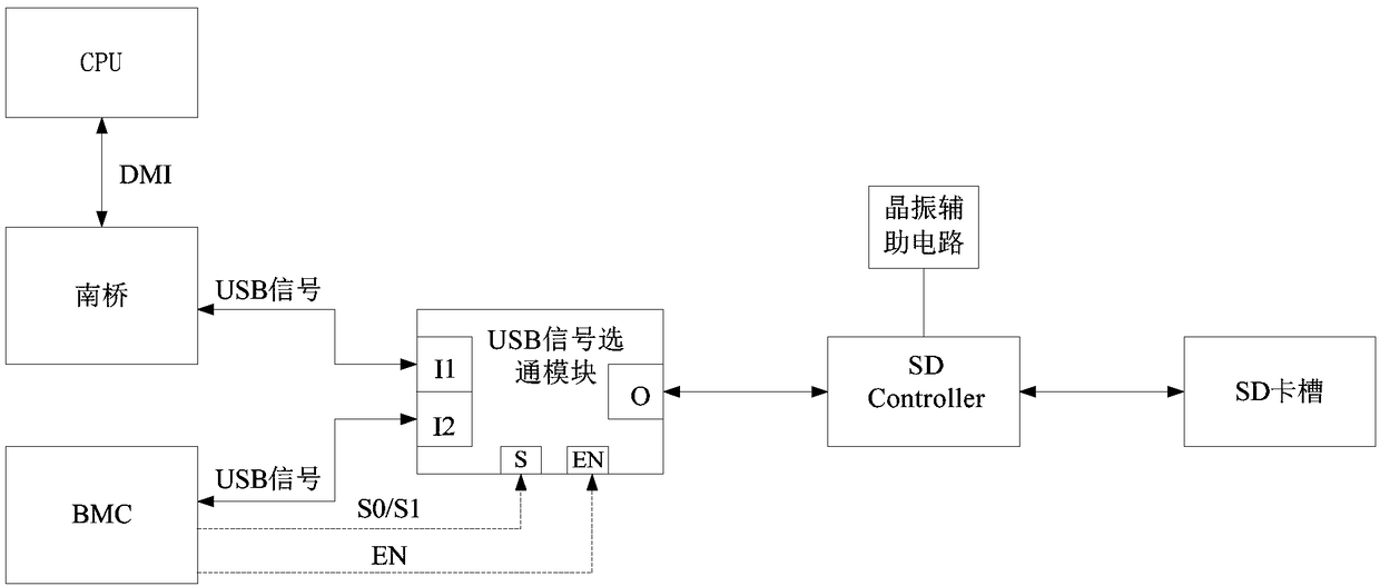
[0051] Further, in order to enable the USB signal gating module to selectively conduct USB signals sent in different application scenarios, a signal control terminal, at least two input terminals and an output terminal may be provided on the USB signal gating module. Among them, at least two input termina...


PUM


Abstract

The invention discloses an SD card system applied to a server mainboard and a design method and the SD card system. The SD card system comprises a USB signal gating module, an SD Controller and an SDcard slot, wherein the USB signal gating module at least comprises two input ends and one output end; and the output end of the USB signal gating module is connected with the SD Controller and the SDcard slot in sequence. The design method comprises the following steps of: setting the USB signal gating module on the server mainboard to ensure that USB signals are connected with the SD Controllerthrough the USB signal gating module; and selectively gating the USB signals by utilizing the USB signal gating module. Through structural design of the SD card system, the occupation of mainboard PCBspace can be greatly decreased, benefit is brought to improve the device density of the server mainboard, and benefit is brought to reduce the comprehensive cost of the SD card system.

Description

technical field [0001] The present application relates to the technical field of server board design, in particular to an SD card system applied to a server board and a design method thereof. Background technique [0002] SD (Secure Digital Memory Card, Secure Digital Card) card is a storage device based on semiconductor flash memory technology, which is widely used in various portable devices and servers. In the field of server board design, in order to realize the connection between the server main board and the external SD card, an SD card slot is usually reserved in the design of the server main board for placing the SD card. SD cards commonly used in servers generally include two types, which are respectively connected to the South Bridge and BMC (Baseboard Management Controller, Baseboard Management Controller). Among them, the SD card connected to the South Bridge is usually built with the server manufacturer's introduction to the server product, user operation guide...

Claims


Application Information

Patent Timeline
Patent Type & Authority Applications(China)
IPC IPC(8): G06F13/40
CPCG06F13/4068G06F2213/0042
Inventor 张国强赵伟涛
Owner ZHENGZHOU YUNHAI INFORMATION TECH CO LTD
Why Eureka
Try Eureka