

Reticulated shell structure modeling method
A technology of structural modeling and reticulated shells, applied in special data processing applications, instruments, electrical digital data processing, etc., can solve problems such as difficult to guide manufacturing and installation, complex space layout, and insufficient model continuity, so as to improve production efficiency , the effect of improving modeling efficiency
Active Publication Date: 2018-09-28
CHINA POWER CONSRTUCTION GRP GUIYANG SURVEY & DESIGN INST CO LTD
View PDF4 Cites 6 Cited by
- Summary
- Abstract
- Description
- Claims
- Application Information
AI Technical Summary
Problems solved by technology
[0003] When traditional CAD software is used for reticulated shell structure design, due to the large number of reticulated shell structural members and complex spatial layout, the conventional two-dimensional diagram expression method cannot completely and accurately express the design information, especially the layout of the rods on the nodes
Because the deviation of the geometric dimensions of the members and nodes and the deviation of the curved surface have a great influence on the internal force, overall stability and construction accuracy of the reticulated shell, it brings certain difficulties to the structural design and construction, resulting in insufficient expression of component information and difficult Guidance on manufacturing and installation, engineering quantity statistics, time-consuming and labor-intensive issues
The traditional design method gives limited information on members and nodes, which cannot be accurate to the machining accuracy, and it is difficult to provide useful help for the installation and positioning of components on the construction site, and it is also impossible to perform space collision checks
For example, the design often uses TEKLA, MST and other steel grid design and calculation software, focusing on the structural calculation and analysis of the grid, the continuity of the model is not enough, and there is still a distance for refined modeling
Therefore, when the number of components reaches the order of tens of thousands, it takes a lot of manpower and material resources to refine the modeling of massive components
Method used
View moreImage
Smart ImageViewing Examples

Examples
Embodiment
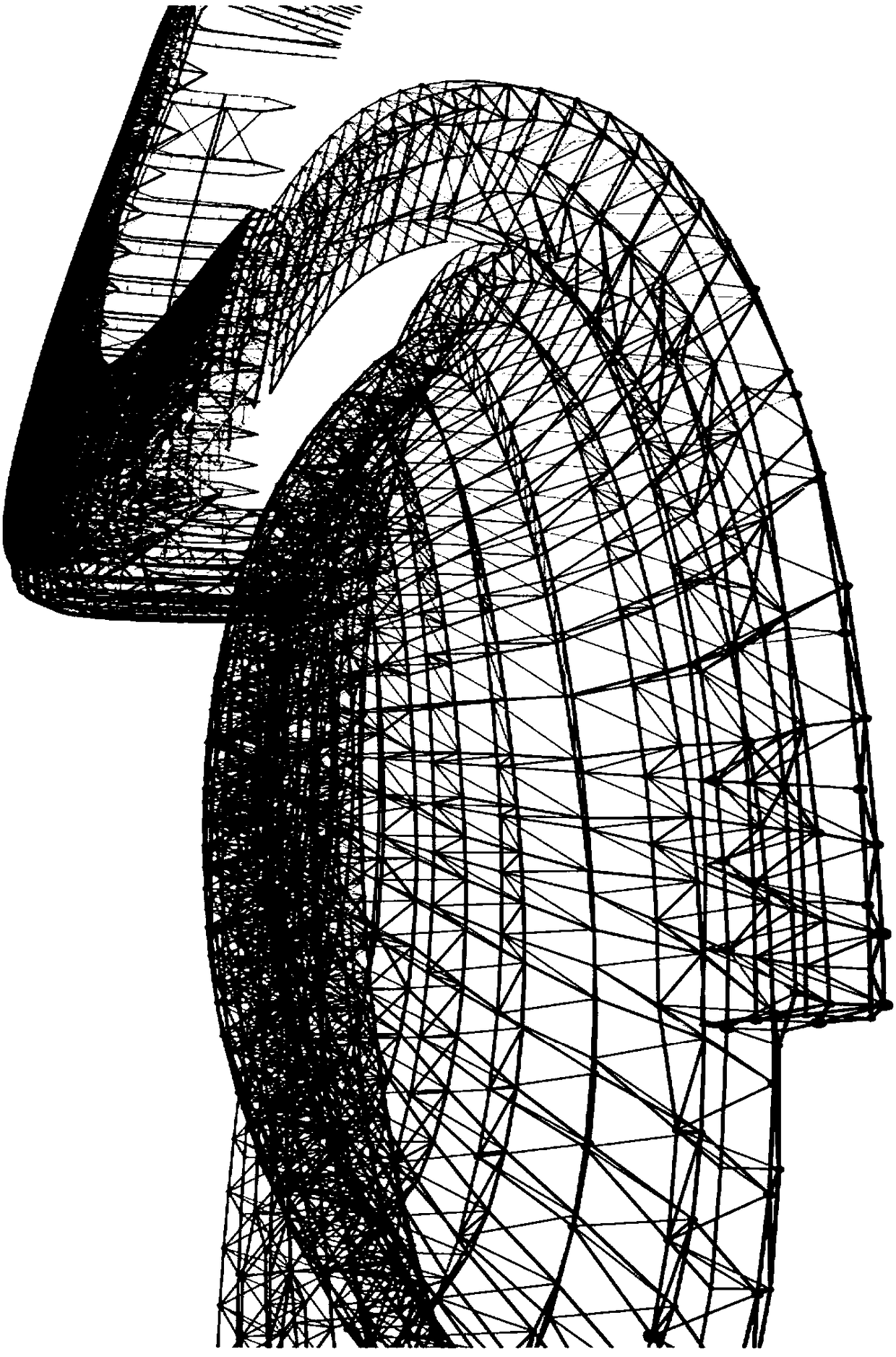
[0063] As mentioned above, the present invention has been successfully applied in the reticulated shell structure design of Shaowu Sports Center Project in Fujian Province, and achieved good results, such as figure 2 shown.
[0064] To sum up, compared with the existing reticulated shell structure design method, the present invention combines the CATIA knowledge engineering function and related specification content, and according to the calculation and analysis results, can quickly create a large number of 3D models of reticulated shell structural components, which greatly improves the Modeling efficiency.
Login to View More PUM
 Abstract
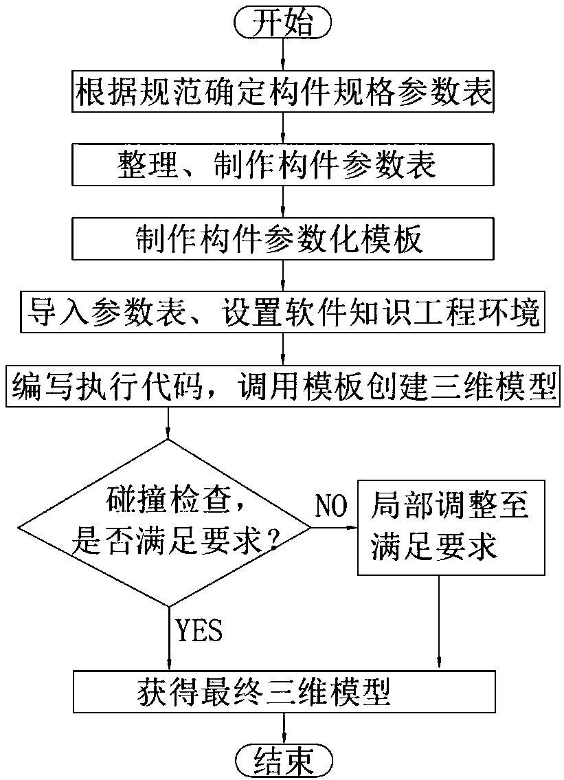
The invention provides a reticulated shell structure modeling method. The method comprises the following steps of determining a required member specification parameter table, creating the member specification parameter table as a member parameter table, creating a member parametric template by using the member parameter table, and importing the parametric template; and setting a calling environment, creating a three-dimensional model, and performing collision detection on the three-dimensional model. Reticulated shell structure three-dimensional models of massive members can be quickly built,so that the modeling efficiency is greatly improved; the model precision is required to reach the member processing level, and information of each member can be subjected to statistics accurately, thereby achieving the purpose of high-precision modeling; spatial collision check can be performed based on the reticulated shell structure three-dimensional models, thereby avoiding mistake, omission, collision and deficiency of reticulated shells; and the three-dimensional models can be applied to the member processing discharging and the field construction installation locating, thereby achievingthe purposes of improving the production efficiency and guiding the reticulated shell construction.
Description
technical field [0001] The invention relates to a method for modeling a reticulated shell structure, which belongs to the technical field of industrial and civil buildings. Background technique [0002] The reticulated shell structure is a curved grid structure, which has the characteristics of both the bar system structure and the thin shell structure. The force is reasonable, and it can realize a large span and a beautiful appearance at the same time, and can use factory prefabricated components to realize industrial production. , the comprehensive technical and economic indicators are good, and it is a spatial structure with good development prospects. [0003] When traditional CAD software is used for reticulated shell structure design, due to the large number of reticulated shell structural members and complex spatial layout, the conventional two-dimensional diagram expression method cannot completely and accurately express the design information, especially the arrange...
Claims
Login to View More Application Information
Patent Timeline
 Patent Type & AuthorityApplications(China)
IPC IPC(8): G06F17/50
CPCG06F30/13
Inventor李水生刘孟雯王正清严沾谋
OwnerCHINA POWER CONSRTUCTION GRP GUIYANG SURVEY & DESIGN INST CO LTD