Audio circuit and system
A circuit and audio technology, applied in the field of audio system, can solve the problems affecting the output sound quality and timbre details of the full-frequency audio system, and the difficulty in the design of the full-frequency audio system, so as to broaden the low-frequency response and increase the system damping , Eliminate the effect of frequency amplitude distortion and nonlinear distortion
- Summary
- Abstract
- Description
- Claims
- Application Information
AI Technical Summary
Problems solved by technology
Method used
Image
Examples
Embodiment 1
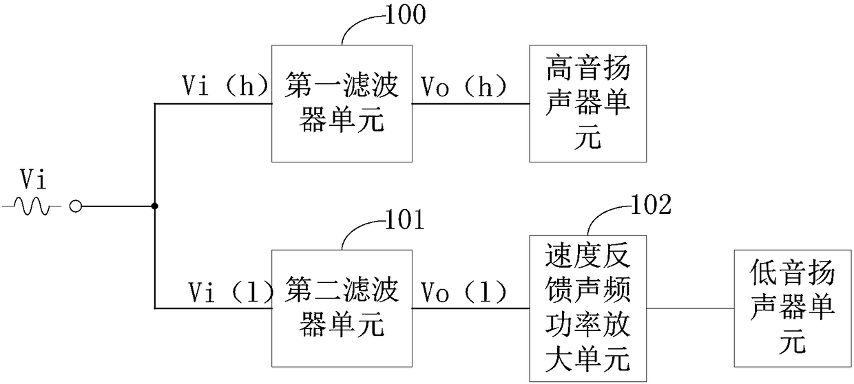
[0107] figure 1 It is a schematic diagram of the module connection of the audio circuit of Embodiment 1, such as figure 1 As shown, the sound circuit includes a first filter unit 100, a second filter unit 101 and a speed feedback audio power amplification unit 102;
[0108] The input terminal Vi(h) of the first filter unit 100 and the input terminal Vi(l) of the second filter unit 101 are both used to input the same sound source signal Vi;
[0109] After the first filter unit 100 and the second filter unit 101 receive the sound source signal Vi, the first filter unit 100 and the second filter unit 101 respectively filter the sound source signal Vi independently. Wherein, the first filter unit 100 is used to separate the high frequency range from the sound source signal Vi, and the second filter unit 101 is used to separate the low frequency range from the sound source signal Vi.
[0110] The output terminal Vo(h) of the first filter unit 100 is used to connect the tweeter un...
Embodiment 2
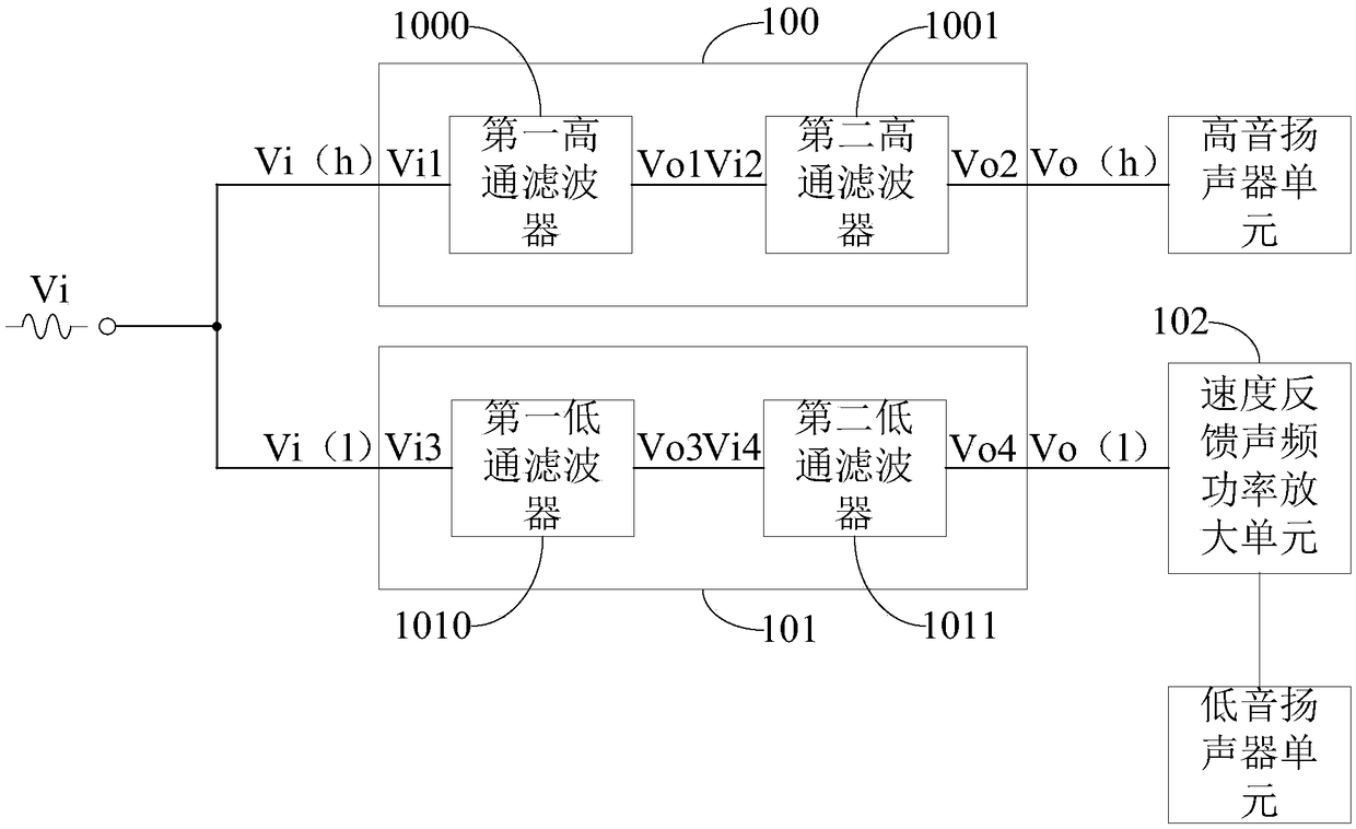
[0119] figure 2 It is a schematic diagram of the connection of the audio circuit module of Embodiment 2, such as figure 2 As shown, the first filter unit 100 includes a first high-pass filter 1000 and a second high-pass filter 1001;
[0120] The output terminal Vo1 of the first high-pass filter 1000 is connected to the input terminal Vi2 of the second high-pass filter 1001; wherein, the input terminal Vi1 of the first high-pass filter 1000 is the input terminal Vi(h) of the first filter unit 100, and the first high-pass filter 1000 is the input terminal Vi(h). The output terminal Vo2 of the second high-pass filter 1001 is the output terminal Vo(h) of the first filter unit 100 .
[0121] Wherein, both the first high-pass filter 1000 and the second high-pass filter 1001 are high-pass active filters, and the frequency division points of the first high-pass filter 1000 and the second high-pass filter 1001 are the same. Optionally, the high-pass active filter is a Butterworth f...
Embodiment 3
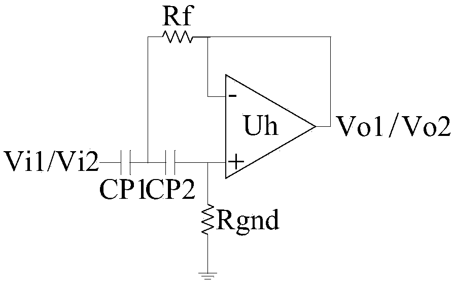
[0129] image 3 It is a schematic diagram of the circuit structure of the first high-pass filter or the second high-pass filter, such as image 3 As shown, the first high-pass filter 1000 and the second high-pass filter 1001 both include an operational amplifier Uh, a feedback resistor Rf, a filter resistor Rgnd, a first filter capacitor CP1 and a second filter capacitor CP2;
[0130] One end of the first filter capacitor CP1 is the input terminal (Vi1 and Vi2) of the first high-pass filter 1000 and the second high-pass filter 1001, the other end is connected to one end of the second filter capacitor CP2, and the other end of the second filter capacitor CP2 is connected to The non-inverting input terminal of the operational amplifier Uh;
[0131] The non-inverting input terminal of the operational amplifier Uh is grounded through the filter resistor Rgnd;
[0132] The output terminal of the operational amplifier Uh is connected to the inverting input terminal of the operatio...
PUM
 Abstract
Description
Claims
Application Information
 - R&D
- Intellectual Property
- Life Sciences
- Materials
- Tech Scout
- Unparalleled Data Quality
- Higher Quality Content
- 60% Fewer Hallucinations
Browse by: Latest US Patents, China's latest patents, Technical Efficacy Thesaurus, Application Domain, Technology Topic, Popular Technical Reports.
© 2025 PatSnap. All rights reserved.Legal|Privacy policy|Modern Slavery Act Transparency Statement|Sitemap|About US| Contact US: help@patsnap.com


