
Cu-Ga ALLOY SPUTTERING TARGET MANUFACTURING METHOD, AND Cu-Ga ALLOY SPUTTERING TARGET

A manufacturing method and sputtering target technology, which are applied in sputtering coating, metal material coating process, transportation and packaging, etc., can solve problems of different degrees and characteristics, and achieve the effect of suppressing damage and high production efficiency

Active Publication Date: 2018-09-28
MITSUBISHI MATERIALS CORP
View PDF12 Cites 0 Cited by
  • Summary
  • Abstract
  • Description
  • Claims
  • Application Information

AI Technical Summary

Problems solved by technology

[0020] In addition, when a Cu-Ga alloy sputtering target having a hollow portion such as a cylinder is manufactured by the methods described in Patent Documents 1, 3, and 4, there may be differences in the degree of progress of sintering on the inner peripheral side and the outer peripheral side. The problem of different characteristics

Method used


Image

  • Cu-Ga ALLOY SPUTTERING TARGET MANUFACTURING METHOD, AND Cu-Ga ALLOY SPUTTERING TARGET
  • Cu-Ga ALLOY SPUTTERING TARGET MANUFACTURING METHOD, AND Cu-Ga ALLOY SPUTTERING TARGET
  • Cu-Ga ALLOY SPUTTERING TARGET MANUFACTURING METHOD, AND Cu-Ga ALLOY SPUTTERING TARGET

Examples


Embodiment

[0108] Hereinafter, the result of the evaluation experiment which evaluated the manufacturing method of the Cu-Ga alloy sputtering target which concerns on this invention is demonstrated.

[0109] First, CuGa alloy powder and Cu powder used as raw material powder were prepared, weighed so as to have the composition shown in Table 1, and mixed with a Henschel mixer. At this time, the content of the Cu powder in the raw material powder was adjusted to the amount shown in Table 1.

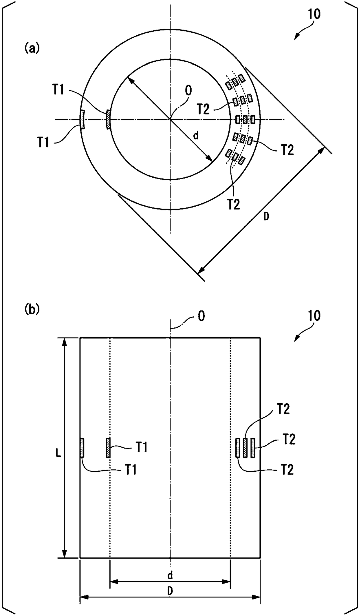
[0110]The powdered raw material was filled into a molding die having a core. The outer mold of the molding die was made of carbon, and the core was made of the materials shown in Table 2. The dimensions of the cavity divided by the outer mold and the core were 230 mm in outer diameter, 170 mm in inner diameter, and 300 mm in axial length.

[0111] And the preliminary sintering process was performed in the atmosphere, holding temperature, and holding time shown in Table 2, and the temporary sintered ...


PUM

PropertyMeasurementUnit
densityaaaaaaaaaa
densityaaaaaaaaaa

Abstract

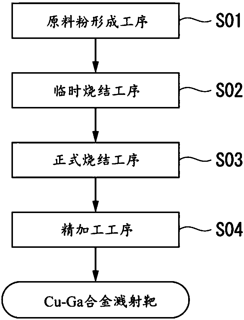
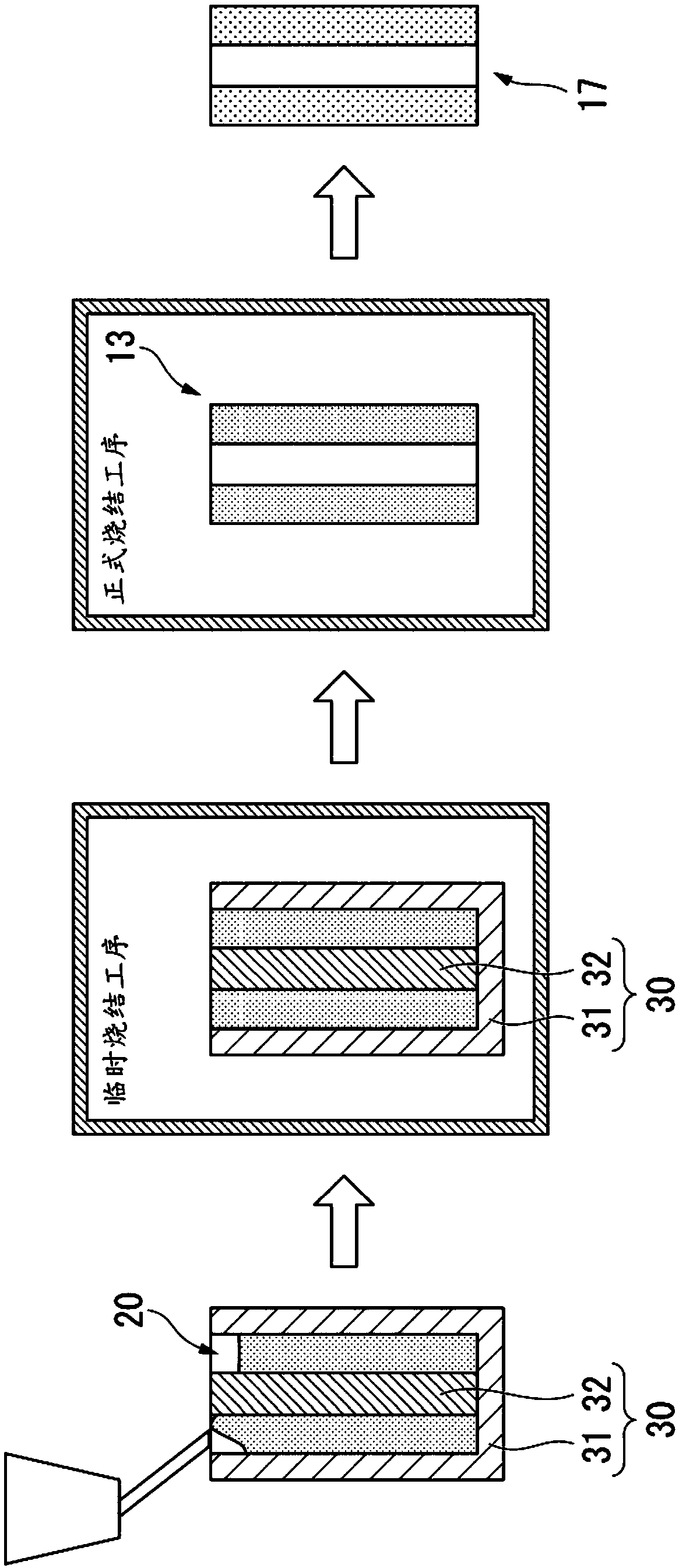
This manufacturing method of a Cu-Ga alloy sputtering target (10), formed from a Cu-Ga alloy and having a hollow portion, involves a calcining step (S02) in which a raw material powder containing at least a CuGA alloy powder is filled into a mold having a core (32) and is heated in a reducing atmosphere to form a calcined body (13), and a main sintering step (S03) in which the core (32) is removedfrom the calcined body (13) and said calcined body (13) is heated in a reducing atmosphere to form a sintered body, wherein, as the core (32) in the calcining step (S02), a core is used that is configured from a material having a linear thermal expansion coefficient greater than that of the Cu-Ga alloy configuring the Cu-Ga alloy sputtering target (10), and, by being maintained at a temperature between 100 DEG C and 600 DEG C for between 10 minutes and 10 hours, the calcined body (13) is formed.

Description

technical field [0001] This invention relates to the manufacturing method of the Cu-Ga alloy sputtering target which has hollow parts, such as a cylindrical shape, and a Cu-Ga alloy sputtering target, for example. [0002] This application claims priority based on Patent Application No. 2016-019282 filed in Japan on February 3, 2016 and Patent Application No. 2016-250827 filed in Japan on December 26, 2016, and the contents thereof are incorporated herein. Background technique [0003] Conventionally, as a thin-film solar cell made of a compound semiconductor, a CIGS-based solar cell including a light-absorbing layer made of a Cu-In-Ga-Se quaternary alloy thin film has been provided. [0004] Among them, as a method of forming a light-absorbing layer composed of a Cu—In—Ga—Se quaternary alloy thin film, a method of forming a film by a vapor deposition method is known. A solar cell having a light-absorbing layer formed by a vapor deposition method has advantages such as high...

Claims


Application Information

Patent Timeline
Patent Type & Authority Applications(China)
IPC IPC(8): C23C14/34B22F3/02B22F3/10B22F5/10C22C1/04C22C9/00C22C28/00
CPCB22F5/10C22C9/00B22F2998/10B22F3/1017C22C1/0425C23C14/3414B22F2009/041Y10T428/12479B22F3/1007B22F5/106B22F2301/10
Inventor 吉田勇气植田稔晃森晓
Owner MITSUBISHI MATERIALS CORP
Learn More