
Piston-cylinder unit

A piston cylinder and assembly technology, which is applied to the direction of piston, piston ring, cylindrical piston, etc., can solve problems such as wear and stopper noise

Active Publication Date: 2018-09-28
ZF FRIEDRICHSHAFEN AG
View PDF9 Cites 3 Cited by
  • Summary
  • Abstract
  • Description
  • Claims
  • Application Information

AI Technical Summary

Problems solved by technology

[0006] This piston ring has the disadvantage that audible stop noises are generated when the piston ring protrudes into the reduced inner diameter
Despite the use of harder materials, there is also significant wear

Method used


Image

  • Piston-cylinder unit
  • Piston-cylinder unit
  • Piston-cylinder unit

Examples


Embodiment Construction

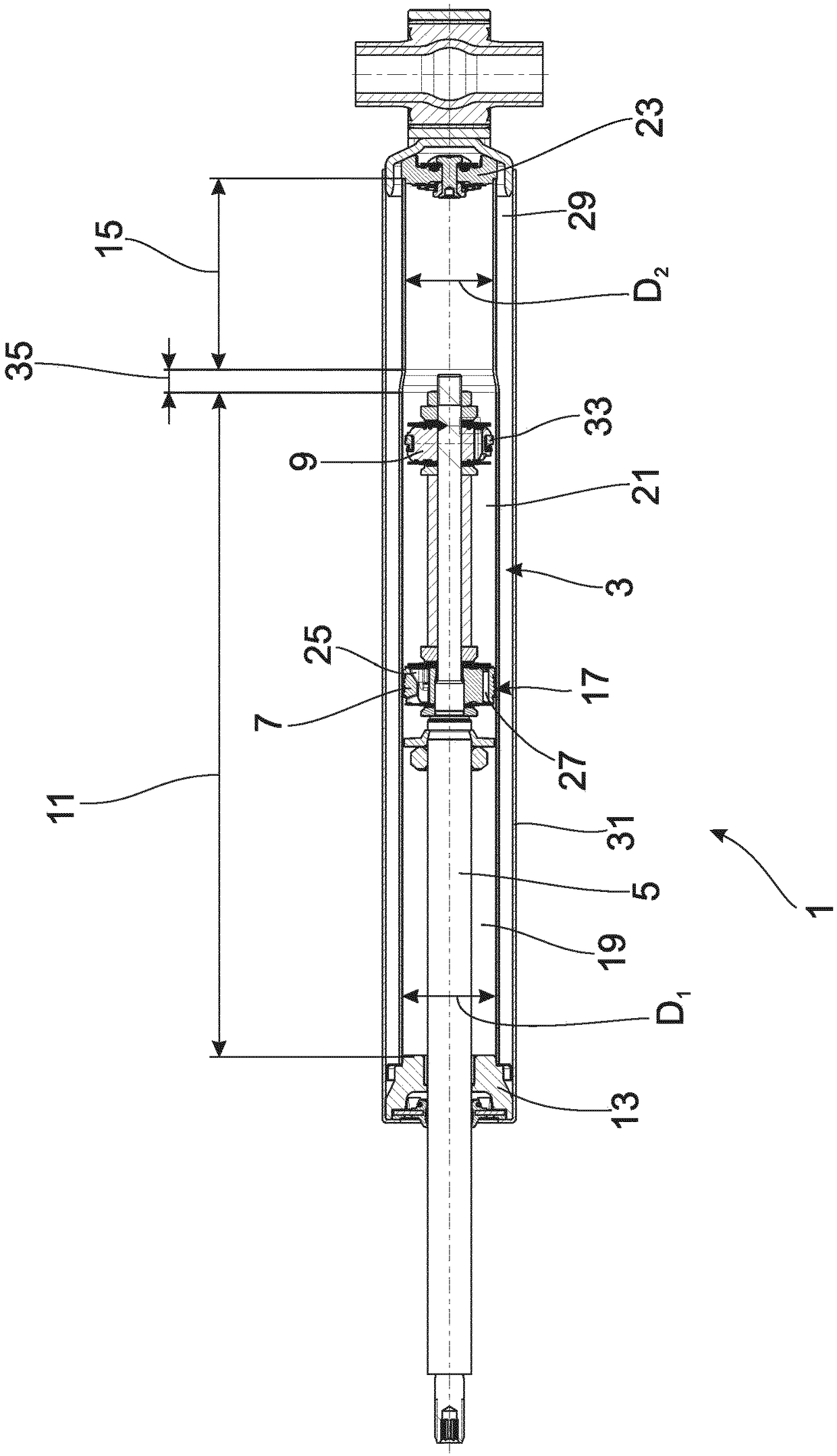
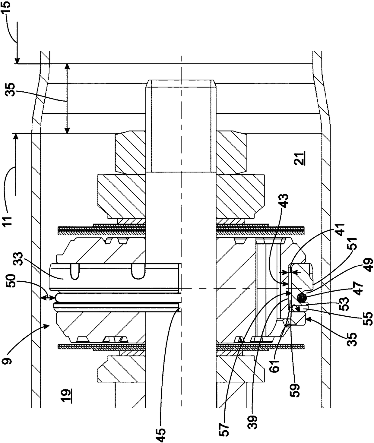
[0024] figure 1 is a possible implementation of the piston-cylinder assembly 1 according to the invention. A piston rod 5 is mounted axially displaceable on the cylinder 3 , on which piston rod a first piston 7 and a second piston 9 arranged at an axial distance therefrom are arranged. Usually, the arrangement of the two pistons 7 , 9 is fixed, but the invention can also be implemented with one or both pistons 7 , 9 displaceably mounted in the region of the piston rod 5 .

[0025] Said cylinder 3 comprises a first longitudinal section 11 having a first diameter D1. In this exemplary embodiment, the first longitudinal section 11 is closed at the end by a piston rod guide 13 . Adjacent at the opposite end is a second longitudinal section 15 having a second diameter D2 , wherein the second diameter D2 is smaller than the first diameter D1 .

[0026] The two pistons 7, 9 also have different nominal diameters. The first piston 7 is adapted to the larger diameter D1 of the first...


PUM


Abstract

Disclosed is a piston-cylinder unit (1) comprising a piston rod (5) on which at least one piston (9) is arranged that has a radially elastic piston ring (33) on an outer lateral surface (37); depending on the stroke position of the piston rod (5), the piston ring (33) plunges into a cylinder (11) and has a smaller diameter (D2) therein than in a stroke position in which the piston (9) is outside the cylinder (3); the piston ring (33) includes a stop (47) which determines a maximum diameter of the piston ring (33).

Description

technical field [0001] The invention relates to a piston-cylinder assembly according to the preamble of claim 1 . Background technique [0002] For example, US Pat. No. 3,175,645 discloses a piston-cylinder assembly with a piston fastened to a piston rod, which protrudes into the cylinder starting from a defined lift position. In this variant, the cylinder is formed by a cap-shaped component that is fastened in the outer cylinder. However, it is known to alternatively form the cap-shaped component from a longitudinal section with a reduced diameter of the outer cylinder. [0003] Regardless of the design of the cylinder, the piston is sealed against the cylinder inner wall by means of a piston ring inside the outer side of the piston. In this case, the piston ring is radially prestressed. [0004] When the piston is outside the cylinder, the piston ring expands radially. Each time it is inserted into the cylinder, the piston ring must be reduced again to its tensioned si...

Claims


Application Information

Patent Timeline
Patent Type & Authority Applications(China)
IPC IPC(8): F16F9/36F16F9/48F16J1/00F16J15/322
CPCF16F9/368F16J1/008F16J15/322F16F9/483F16F9/3235F16F2224/0208F16F2230/30F16J9/12
Inventor A·阿尔策R·舒尔特
Owner ZF FRIEDRICHSHAFEN AG
Learn More